


3-5. Disassembly, Reassembly and Lubrication
CLP-621 & CLP-631
3-12
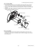
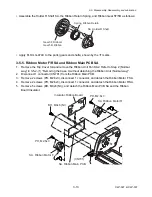
3-5-4. Ribbon Gears
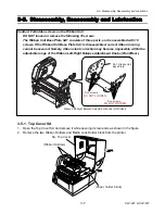
1. Remove the Top Cover SA and remove the Ribbon Unit Fan SA2. Refer to Step 2 (Normal
way) in 3-5-2-(1) “Removing the Case U without detaching the Ribbon Unit (Normal way)”.
2. On the front (ribbon take-up) side, remove 1 screw (NO. 0, TFH, M2x3 (NI)) and 1 Ribbon
Washer Plate. Then, remove the Holder R Shaft SA, Ribbon Return Spring, and Ribbon Gear
5F in that order.
3. Also on the front side, disengage 1 E-ring and remove the Ribbon Gear 2, Ribbon Gear 1,
Ribbon Gear 3, and Ribbon Gear 4 in that order.
4. On the rear (ribbon supply) side, remove 1 screw (No. 0, TFH, M2x3 (NI)) and 1 Ribbon
Washer Plate. Then, remove the Holder R Shaft SA, Ribbon Return Spring, and Ribbon Gear
5R in that order.
5. Also on the rear side, disengage 1 E-ring and remove the Ribbon Gear 2, Ribbon Gear 1,
Ribbon Gear 3, and Ribbon Gear 4 in that order.
Plate, Ribbon Washer
Plate, Ribbon Washer
SA, Holder R Shaft
SA, Holder R Shaft
Spring, Ribbon Return
Spring, Ribbon Return
Gear 5R, Ribbon
Gear 5F, Ribbon
Gear 4, Ribbon
Gear 4, Ribbon
Gear 1, Ribbon
Gear 3, Ribbon
Gear 2, Ribbon
E-Ring, 4
Gear 1, Ribbon
Gear 2, Ribbon
Gear 3, Ribbon
E-Ring, 4
FLOIL G-474C
No. 0, TFH, M2x3 (NI)
No. 0, TFH, M2x3 (NI)
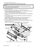
Notes on reassembling:
• Distinguish the Ribbon Gear 5F from the Ribbon Gear 5R, referring to the following figure.
Gear 5F, Ribbon
Gear 5R, Ribbon
Projection
Summary of Contents for CLP-621
Page 1: ...Technical Manual CLP 621 CLP 631 Thermal Transfer Barcode Label Printer JM74961 00F 1 00E 0701...
Page 2: ...CLP 621 CLP 631 ii Copyright 2007 by CITIZEN SYSTEMS JAPAN CO LTD...
Page 4: ...CHAPTER 1 SPECIFICATIONS CLP 621 CLP 631...
Page 13: ...CHAPTER 2 OPERATING PRINCIPLES CLP 621 CLP 631...
Page 73: ...CHAPTER 3 DISASSEMBLY AND MAINTENANCE CLP 621 CLP 631...
Page 126: ...CLP 621 CLP 631 CHAPTER 4 TROUBLESHOOTING...
Page 138: ...CLP 621 CLP 631 CHAPTER 5 PARTS LISTS...
Page 166: ...Chapter 5 Parts Lists CLP 621 CLP 631 5 29 DRAWING NO 7 Control Panel Unit Rev 0 4 3 2 1 5...
Page 177: ...Chapter 5 Parts Lists CLP 621 CLP 631 5 40 DRAWING NO 10 Accessories Rev 0 3 2 4 1...
Page 179: ...CHAPTER 6 CIRCUIT DIAGRAMS CLP 621 CLP 631...
Page 208: ...APPENDICES CLP 621 CLP 631...
Page 212: ...B Mounting Diagrams AP 5 CLP 621 CLP 631 Main PCB Solder side...
Page 214: ...B Mounting Diagrams AP 7 CLP 621 CLP 631 B 3 Ribbon Main PCB Parts side Solder side...
Page 217: ......


