


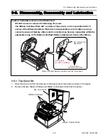


3-5. Disassembly, Reassembly and Lubrication
3-11
CLP-621 & CLP-631
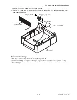
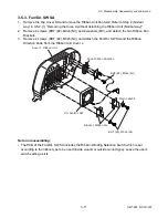
3-5-3. Fan/Dir. SW SA
1. Remove the Top Cover SA and remove the Ribbon Unit Fan SA2. Refer to Step 2 (Normal
way) in 3-5-2-(1) “Removing the Case U without detaching the Ribbon Unit (Normal way)”.
2. Remove 4 screws (BHT (#2), M3x6 (NI)) and 4 washers (M3), and detach the two Ribbon Fan
Brackets.
3. Remove 2 screws (BHT (#2), M3x6 (NI)) and detach the Fan/Dir. SW SA and the Ribbon
Direction Knob from the Ribbon Unit Cover L.
Bracket, Ribbon Fan
Knob, Ribbon Direction
BHT (#2), M3x6 (NI)
Plain, 3x8x0.5
Cover L, Ribbon Unit
SA, Fan/Dir. SW
BHT (#2), M3x6 (NI)
Note on reassembling:
• The PCB of the Fan/Dir. SW SA includes the Ribbon Winding Selection Switch which is set
according to the ribbon type to be used (inside wound or outside wound type). Leave the user’s
switch setting as it is.
Summary of Contents for CLP-621
Page 1: ...Technical Manual CLP 621 CLP 631 Thermal Transfer Barcode Label Printer JM74961 00F 1 00E 0701...
Page 2: ...CLP 621 CLP 631 ii Copyright 2007 by CITIZEN SYSTEMS JAPAN CO LTD...
Page 4: ...CHAPTER 1 SPECIFICATIONS CLP 621 CLP 631...
Page 13: ...CHAPTER 2 OPERATING PRINCIPLES CLP 621 CLP 631...
Page 73: ...CHAPTER 3 DISASSEMBLY AND MAINTENANCE CLP 621 CLP 631...
Page 126: ...CLP 621 CLP 631 CHAPTER 4 TROUBLESHOOTING...
Page 138: ...CLP 621 CLP 631 CHAPTER 5 PARTS LISTS...
Page 166: ...Chapter 5 Parts Lists CLP 621 CLP 631 5 29 DRAWING NO 7 Control Panel Unit Rev 0 4 3 2 1 5...
Page 177: ...Chapter 5 Parts Lists CLP 621 CLP 631 5 40 DRAWING NO 10 Accessories Rev 0 3 2 4 1...
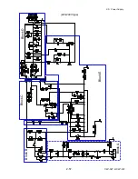
Page 179: ...CHAPTER 6 CIRCUIT DIAGRAMS CLP 621 CLP 631...
Page 208: ...APPENDICES CLP 621 CLP 631...
Page 212: ...B Mounting Diagrams AP 5 CLP 621 CLP 631 Main PCB Solder side...
Page 214: ...B Mounting Diagrams AP 7 CLP 621 CLP 631 B 3 Ribbon Main PCB Parts side Solder side...
Page 217: ......


