


3-5. Disassembly, Reassembly and Lubrication
CLP-621 & CLP-631
3-10
(
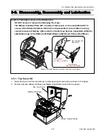
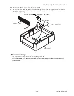
2) Removing the Case U after detaching the Ribbon Unit
Caution: Once the Ribbon Unit is removed, you need to recheck if ribbon wrinkles
appear or not. If ribbon wrinkles are found, correct them referring to
“Removing Ribbon Wrinkle” on page
. Normally, adjustment with the
Ribbon Left-Right Balance Adjustment Knobs (Front/Rear) will remove ribbon
wrinkle.
1. Remove the Top Cover SA. Refer to 3-5-1 “Top Cover SA”.
2. Remove 2 screws (PH, M3x6) and detach the Ribbon Unit by lifting it upward. At this time,
disconnect 1 connector (CN701) from the Ribbon Main PCB.
3. Remove 1 screw (PH, M3x3) and detach the Motor Cover.
4. Remove 5 screws (PHT (BH2T), M3x14).
5. Release the Head Open Lever (blue color) to open the Head Unit, and then carefully
detach the Case U Unit by lifting it upward.
PH, M3x3
Cover, Motor
PH, M3x6
Unit, Ribbon
PHT (BH2T), M3x14
(Ribbon Left-Right Balance
Adjustment Knob (Rear))
(Ribbon Left-Right Balance
Adjustment Knob (Front))
(Case U Unit)
(CN701)
Summary of Contents for CLP-621
Page 1: ...Technical Manual CLP 621 CLP 631 Thermal Transfer Barcode Label Printer JM74961 00F 1 00E 0701...
Page 2: ...CLP 621 CLP 631 ii Copyright 2007 by CITIZEN SYSTEMS JAPAN CO LTD...
Page 4: ...CHAPTER 1 SPECIFICATIONS CLP 621 CLP 631...
Page 13: ...CHAPTER 2 OPERATING PRINCIPLES CLP 621 CLP 631...
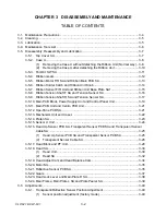
Page 73: ...CHAPTER 3 DISASSEMBLY AND MAINTENANCE CLP 621 CLP 631...
Page 126: ...CLP 621 CLP 631 CHAPTER 4 TROUBLESHOOTING...
Page 138: ...CLP 621 CLP 631 CHAPTER 5 PARTS LISTS...
Page 166: ...Chapter 5 Parts Lists CLP 621 CLP 631 5 29 DRAWING NO 7 Control Panel Unit Rev 0 4 3 2 1 5...
Page 177: ...Chapter 5 Parts Lists CLP 621 CLP 631 5 40 DRAWING NO 10 Accessories Rev 0 3 2 4 1...
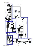
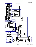
Page 179: ...CHAPTER 6 CIRCUIT DIAGRAMS CLP 621 CLP 631...
Page 208: ...APPENDICES CLP 621 CLP 631...
Page 212: ...B Mounting Diagrams AP 5 CLP 621 CLP 631 Main PCB Solder side...
Page 214: ...B Mounting Diagrams AP 7 CLP 621 CLP 631 B 3 Ribbon Main PCB Parts side Solder side...
Page 217: ......


