Chapter 2 Operating Principles
2-2.
Operation of Control Parts
CL-E700 series
2-30
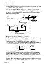
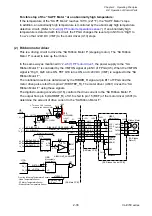
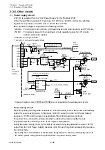
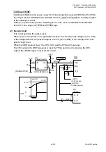
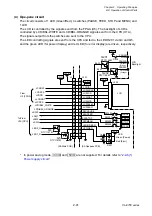
If the temperature of the “SA Ribbon Motor F” exceeds a certain level, the ribbon motor
temperature sensor output voltage becomes lower than the reference voltage, and the pin 1 of
U8A goes to “Low” level. At this time, pin K1 (nTMPERR) is “Low” and the FPGA (U5) detects
an abnormally high temperature.
In this abnormal state, the printer stops +24V DC supply to the “SA Ribbon Motor F”. Also, it
stops +24V DC supply to the “SA PF Motor” and “SA Head”.
(6)
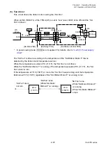
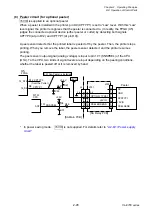
Ribbon tension sensor (SA Ribbon Sensor)
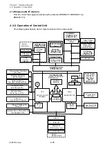
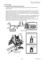
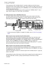
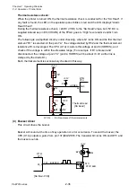
The ribbon tension sensor consists of two photointerrupters and is located on the ribbon
take-up side (front side) of the “Unit Ribbon”. It is used to detect the ribbon tension on the
ribbon take-up side to maintain the ribbon tension on the take-up side constant.
* In power saving mode, +3VIO is not supplied. For details, refer to “
”.
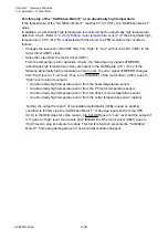
Ribbon tension sensor operation when the ribbon slacks:
During printing, the ribbon is fed forward together with the media. Thus, the ribbon on the
take-up side slacks and the projections of the “SA Ribbon Tension Shaft F” come off the
photointerrupters (PS401 and PS402) on the “SA Ribbon Sensor”. Thus, the photointerrupters
turn ON, and pin 26 (RIBSENS_R1) and pin 31 (RIBSENS_R2) go to “High” level.
At this time, the printer increases the rotational speed of the “SA Ribbon Motor F” to wind the
take-up side ribbon faster to give more tension to the ribbon.
Ribbon tension sensor operation when the ribbon tightens:
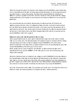
When the ribbon is wound and tightened, the projections of the “SA Ribbon Tension Shaft F”
are inserted into the photointerrupters (PS401 and PS402) and pin 26 (RIBSENS_R1) and pin
31 (RIBSENS_R2) go to “Low” level.
At this time, the printer decreases the rotational speed of the “SA Ribbon Motor F” to give less
tension to the ribbon.
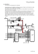
During printing, the above ribbon tension control cycle is repeated to give constand tension to
the take-up side ribbon. Further, by using 2 photointerrupters, ribbon tension is finely
controlled.
[SA Ribbon Sensor]
Ribbon
Sensor1
2
3
1
PT401
PS401
R401
4
Ribbon Sensor
2
3
1
J606
4
[SA Ribbon
Control PCB]
11
10
J601
CPU
26
31
Ribbon
Sensor2
PS402
R402
1
1
+3.3V
RIBSENS_R1
RIBSENS_R2
C104
RIBSENS_R1
RA17
1
2
U12A
C105
R77
R78
3
4
U12B
RIBSENS_R2
[SA Main PCB]
14-16
14-16
J304
22
21
J301
22
21
8
8
RIBSENS_R1
RIBSENS_R2
3-6
J4
[SA Relay PCB]
U1A
3-6
11
10
+3VIO
+3VIO
+3VIO
P6_5
P6_6
Summary of Contents for CL-E700 Series
Page 1: ...Technical Manual CL E700 series Thermal Transfer Printer...
Page 5: ...Chapter 1 Specifications 1 1 CL E700 series CHAPTER 1 SPECIFICATIONS...
Page 15: ...Chapter 2 Operating Principles 2 1 CL E700 series CHAPTER 2 OPERATING PRINCIPLES...
Page 87: ...Chapter 3 Disassembly and Maintenance 3 1 CL E700 series CHAPTER 3 DISASSEMBLY AND MAINTENANCE...
Page 151: ...Chapter 4 Troubleshooting 4 1 CL E700 series CHAPTER 4 TROUBLESHOOTING...
Page 167: ...Chapter 5 Parts Lists CL E700 series CHAPTER 5 PARTS LISTS...
Page 172: ...Chapter 5 Parts Lists CL E700 series 5 6 DRAWING NO 1 General Assembly Rev 0...
Page 195: ...Chapter 5 Parts Lists 5 29 CL E700 series DRAWING NO 7 Unit Opepane Rev 0...
Page 203: ...Chapter 5 Parts Lists 5 37 CL E700 series DRAWING NO 9 SA2 Ribbon Unit Fan Rev 0...
Page 206: ...Chapter 5 Parts Lists CL E700 series 5 40 DRAWING NO 10 Accessories Rev 0 3 2 4 1 1 1 2 1 3...
Page 208: ...Chapter 6 Circuit Diagrams 6 1 CL E700 series CHAPTER 6 CIRCUIT DIAGRAMS...
Page 230: ...Appendices AP 1 CL E700 series APPENDICES...
Page 233: ...Appendices A Mounting Diagrams CL E700 series AP 4 2 Solder side...


