


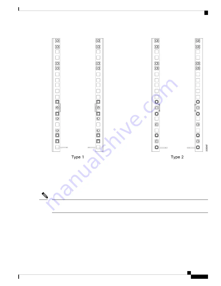
Figure 18: Rear Rail Kit Layout, Both Rail Kits
Installing the Top Cable Management Arms
The accessory kit contains two cable management assemblies, each one consisting of three cable management
arms and three cable ties. The cable management assemblies facilitate gathering and organizing the chassis
power cables.
The server also has cable management trays (UCSX-9508-CMA) for gathering and organizing the cables
from the IFMs and X-Fabric modules.
Note
In this topic, top and bottom refer to the location on the chassis. Cable management arms are interchangeable,
so there is no specific top and bottom cable arm.
Each cable management assembly is for a set of three PSUs. The top cable management arms attach to the
top set of PSUs in the chassis. The bottom cable management arms attach a grounding bracket for the bottom
set of PSUs, so the installation procedure is slightly different. See
Installing the Ground Bracket and Bottom
Cable Management Arms, on page 39
.
Use this task to attach the cable management assemblies to the chassis before installing the chassis in the rack.
Cisco UCS X9508 Server Chassis Installation Guide
37
Installation
Installing the Top Cable Management Arms
Summary of Contents for UCS X9508
Page 6: ...Cisco UCS X9508 Server Chassis Installation Guide vi Contents ...
Page 26: ...Cisco UCS X9508 Server Chassis Installation Guide 18 Overview Interpreting LEDs ...
Page 31: ...Cisco UCS X9508 Server Chassis Installation Guide 23 Installation Handling the Chassis ...
Page 64: ...Cisco UCS X9508 Server Chassis Installation Guide 56 Installation Repacking the Chassis ...
Page 124: ...Cisco UCS X9508 Server Chassis Installation Guide 116 Technical Specifications Switzerland ...