3-13
Cisco UCS S3260 Storage Server Chassis Installation and Service Guide
Chapter 3 Maintaining the System
Preparing for System Component Installation or Replacement
Removing a Server Node Cover
To remove a server node cover, see the service note for your server node:
Cisco UCS C3X60 M3 Server Node For Cisco UCS S3260 System Service Note
Cisco UCS C3X60 M4 Server Node For Cisco UCS S3260 System Service Note
Cisco UCS S3260 M5 Server Node For Cisco UCS S3260 System Service Note
Removing an I/O Expander Cover (C3X60 M4 and S3260 M5 Server Nodes Only)
To remove an I/O expander cover, see the C3X60 M4 server node service note:
Cisco UCS C3X60 M4 Server Node For Cisco UCS S3260 System Service Note
Cisco UCS S3260 M5 Server Node For Cisco UCS S3260 System Service Note
Removing an I/O Expander From a Node (C3X60 M4 and S3260 M5 Server Nodes Only)
The I/O expander attaches to the top of the server node. To remove an I/O expander from a server node
so that you can access the components inside the server node, see the server node service note:
Cisco UCS C3X60 M4 Server Node For Cisco UCS S3260 System Service Note
Cisco UCS S3260 M5 Server Node For Cisco UCS S3260 System Service Note
Removing the System I/O Controller (SIOC) Cover
Note
You do not have to slide the system out of the rack to remove the SIOC from the rear of the system.
Step 1
Power off the server node that is paired with the SIOC that you are replacing (SIOC 1 is paired with
server node1; SIOC 2 is paired with server node 2).
Step 2
Remove the SIOC from the system:
a.
Loosen the single captive thumbscrew on the SIOC and then open its two hinged levers to evenly
disengage the SIOC from its backplane connector.
b.
Pull the SIOC from the system and set it on an antistatic work surface.
Step 3
Remove the SIOC cover:
a.
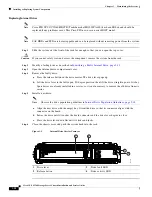
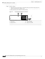
Use a #1 Phillips-head screwdriver to remove the screws that secure the cover. The version 02 SIOC
cover has four securing screws. The Version 03 SIOC cover has six securing screws. See
or
b.
Lift the cover straight up off the SIOC.
Step 4
Reinstall the SIOC cover:
a.
Set the cover back in place.
b.
Replace the four screws that secure the cover.
Step 5
Reinstall the SIOC in the system:
a.
Push the SIOC into its bay until it stops against the internal midplane.
b.
Close the two levers on the SIOC to fully engage the SIOC connector with its midplane.
c.
Tighten the thumbscrew on the SIOC levers.


