


Product Overview 1-27
Physical Description
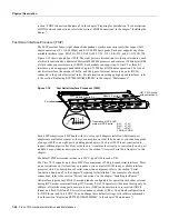
Each FIP provides a single network interface for both multimode and single-mode FDDI networks.
The two FIP connectors are available in any combination of multimode (MIC) or single-mode (FC)
connectors for matching multimode and single-mode fiber in the same FDDI network. The following
combinations are available:
•
CX-FIP-MM—FDDI PHY-A multimode, PHY-B multimode interface processor
•
CX-FIP-MS—FDDI PHY-A multimode, PHY-B single-mode interface processor
•
CX-FIP-SM—FDDI PHY-A single-mode, PHY-B multimode interface processor
•
CX-FIP-SS—FDDI PHY-A single-mode, PHY-B single-mode interface processor
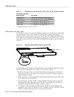
As with the other interface processors, the enabled LED is on when the FIP is enabled for operation.
To the right of the enabled LED, a bank of six LEDs indicate the state of the two physical sublayer
connections (PHY B and PHY A). The left column of three LEDs indicates PHY B; the right column
indicates PHY A. (On the front of the FIP, the left interface is PHY B and the right interface is
PHY A as shown in Figure 1-17.) The state of each B/A pair of LEDs indicates the status of one type
of three possible station connections: dual-homed, single-attach station (SAS), or dual-attach station
(DAS). For complete descriptions of the LED states, refer to the appendix “Reading LED
Indicators.”
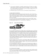
Each FIP provides the interface for connection to a Class A DAS (with primary and secondary rings),
or to a Class B SAS (with only a primary ring). The Cisco 7010 supports up to three FIPs for a
maximum of 3 FDDI network connections. The multimode MIC or single-mode FC ports on the FIP
provide a direct connection to the external FDDI network.
A six-pin mini-DIN connector on the multimode-multimode (CX-FIP-MM) and single-mode
(CX-FIP-SS) FIPs provides the connection for an optical bypass switch. When the interface is shut
down, the bypass switch allows the light signal to pass directly from the receive port to the transmit
port on the bypass switch, completely bypassing the FIP transceivers. The bypass switch does not
repeat the signal, and significant signal loss may occur when transmitting to stations at maximum
distances. Optical bypass switches typically use a six-pin DIN or mini-DIN connector. A
DIN-to-mini-DIN adapter cable (CAB-FMDD) is included with the FIP to allow connection to either
type of connector. For a detailed description of optical bypass and FDDI connections, refer to the
H2007
Optical
bypass port
Single-mode
ports
U23,
microcode
ROM
Multimode
ports
PHY B
U23,
microcode
ROM
PHY A
TX RX
Multimode
port
ENABLED
DH
SAS
DAS
Summary of Contents for TelePresence Server 7010
Page 10: ...x Cisco 7010 Hardware Installation and Maintenence ...
Page 14: ...iv Cisco 7010 Hardware Installation and Maintenance Document Conventions ...
Page 148: ...3 36 Cisco 7010 Hardware Installation and Maintenance Using the Flash Memory Card ...
Page 158: ...4 10 Cisco 7010 Hardware Installation and Maintenance Troubleshooting the Processor Subsystem ...
Page 242: ...5 84 Cisco 7010 Hardware Installation and Maintenance Replacing Internal Components ...
Page 258: ...A 16 Cisco 7010 Hardware Installation and Maintenance MIP Interface Cable Pinouts ...
Page 270: ...B 12 Cisco 7010 Hardware Installation and Maintenance Interface Processor LEDs ...
Page 274: ...C 4 Cisco 7000 Hardware Installation and Maintenance ...
Page 287: ...Index 13 ...


