Product Overview 1-15
Physical Description
EEPROM
An electrically erasable programmable read-only memory (EEPROM) component on the RP (and
on the SP and each interface processor) stores board-specific information such as the board serial
number, part number, controller type, hardware revision, and other details unique to each board. In
addition to this standard information, the RP EEPROM also contains an address allocator, which is
a bank of 40 hardware or media access control (MAC)-level addresses, one for each possible port in
the system. For an explanation of the hardware addressing function, refer to the section “MAC
Address Allocator” in this chapter.
Jumpers
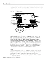
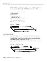
The hardware configuration register is a 50-pin jumper block located at the left front of the board,
when viewing the RP in the orientation shown in Figure 1-9. By installing jumpers on specific pins,
you can define system boot instructions, set broadcast addresses and console baud rates, instruct the
router to perform factory diagnostics at startup, and recover from a lost password.
Jumper J2, which is located near the configuration register, provides write protection for Flash
memory. (See Figure 1-9.) The jumper is installed on J2 by default, which allows you to write to
Flash memory. When the jumper is removed, Flash memory is read-only; you cannot write to Flash
or erase the contents until you replace the jumper.
Jumpers J3 and J4 are set according to the size of the eight system software EPROMs. You need to
reset these jumpers only if you upgrade the system software by replacing the ROMs instead of
downloading the new image, and if the size (capacity) of the new EPROMs is greater than those you
replace.
For a detailed description of all jumper functions and settings, refer to the section “RP and RSP7000
Configurations” in the chapter “Maintenance”
LEDs
The three LEDs on the RP indicate the system and RP status. The normal LED is on when the system
is operational. During normal operation, the CPU halt and boot error LEDs on the RP should be off.
When the system is turned on or restarted, the boot LED goes on for 1 or 2 seconds, then goes off.
The CPU halt LED, which goes on only if the system detects a processor hardware failure, should
never be on. For complete descriptions of the LED states, refer to the appendix “Reading LED
Indicators.”
Serial Ports
Two asynchronous serial ports on the RP, the console and auxiliary ports, provide the means for
connecting a terminal, modem, or other device for configuring and managing the system. A data
circuit-terminating equipment (DCE) EIA/TIA-232 receptacle console port on the RP provides a
direct connection for a console terminal. The adjacent data terminal equipment (DTE) EIA/TIA-232
plug auxiliary port supports flow control and is often used to connect a modem, a channel service
unit (CSU), or other optional equipment for Telnet management of the attached device.
Note
Prior to acceptance by the Electronic Industries Association (EIA) and Telecommunications
Industry Association (TIA) as a standard, EIA/TIA-232 [or 449] was an EIA recommended standard
(RS) known as EIA/TIA-232 [or 449].
Summary of Contents for TelePresence Server 7010
Page 10: ...x Cisco 7010 Hardware Installation and Maintenence ...
Page 14: ...iv Cisco 7010 Hardware Installation and Maintenance Document Conventions ...
Page 148: ...3 36 Cisco 7010 Hardware Installation and Maintenance Using the Flash Memory Card ...
Page 158: ...4 10 Cisco 7010 Hardware Installation and Maintenance Troubleshooting the Processor Subsystem ...
Page 242: ...5 84 Cisco 7010 Hardware Installation and Maintenance Replacing Internal Components ...
Page 258: ...A 16 Cisco 7010 Hardware Installation and Maintenance MIP Interface Cable Pinouts ...
Page 270: ...B 12 Cisco 7010 Hardware Installation and Maintenance Interface Processor LEDs ...
Page 274: ...C 4 Cisco 7000 Hardware Installation and Maintenance ...
Page 287: ...Index 13 ...

