


5-8 Cisco 7010 Hardware Installation and Maintenance
Installing and Configuring Processor Modules
Step 4
Place the back of the interface processor in the slot and align the carrier guides along the
sides of the interface processor with the grooves in the side of the slot. (See Figure 5-1a.)
Step 5
While keeping the interface processor at a 90-degree orientation to the backplane, carefully
slide the interface processor into the slot until the interface processor faceplate makes
contact with the ejector levers.
Step 6
Using your thumbs, simultaneously push both ejector levers inward until they push the
interface processor completely into the slot. The ejectors should be in approximately the
same orientation as the interface processor faceplate. (See Figure 5-1c.)
Step 7
Use a screwdriver to tighten both of the captive installation screws.
Step 8
Attach network interface cables or other devices to the interface ports.
Step 9
Check the status of the interfaces as follows:
•
If this installation is a replacement interface processor, use the show interface or show
controllers [type] command to verify that the system has acknowledged the new
interfaces and brought them up.
•
If the interfaces are new, use the configure command or the setup command facility to
configure the new interface(s). This does not have to be done immediately, but the
interfaces will not be available until you configure them.
Note
Always use the ejector levers when installing or removing processor modules. A module that
is partially seated in the backplane will cause the system to hang and subsequently crash.
Caution
You must turn OFF power to the system before removing or installing an RP or SP (or
SSP). After the chassis power has been turned OFF, the installation and removal procedure is the
same as the preceding steps for replacing interface processors.
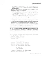
Sample Screen Display for OIR
When you remove and replace CxBus interface processors, the system provides status messages
across the console screen. The messages are only informational. In the following sample display, the
events logged by the system show that an EIP was removed from slot 0, the system reinitialized the
remaining interface processors, and marked the EIP that was removed from slot 0 as down. When
the EIP was reinserted, the system marked the interfaces as up again.
7010#
%OIR-6-REMCARD: Card removed from slot 0, interfaces disabled
%LINK-5-CHANGED: Interface TokenRing2/0, changed state to initializing
%LINK-5-CHANGED: Interface Ethernet0/1, changed state to administratively down
%LINK-5-CHANGED: Interface Ethernet0/5, changed state to administratively down
%LINK-5-CHANGED: Interface TokenRing2/0, changed state to up
7010#
%OIR-6-INSCARD: Card inserted in slot 0, interfaces administratively shut down
%LINK-5-CHANGED: Interface TokenRing2/0, changed state to initializing
%LINK-5-CHANGED: Interface Ethernet0/1, changed state to up
%LINK-5-CHANGED: Interface Ethernet0/5, changed state to up
%LINK-5-CHANGED: Interface TokenRing2/0, changed state to up
Summary of Contents for TelePresence Server 7010
Page 10: ...x Cisco 7010 Hardware Installation and Maintenence ...
Page 14: ...iv Cisco 7010 Hardware Installation and Maintenance Document Conventions ...
Page 148: ...3 36 Cisco 7010 Hardware Installation and Maintenance Using the Flash Memory Card ...
Page 158: ...4 10 Cisco 7010 Hardware Installation and Maintenance Troubleshooting the Processor Subsystem ...
Page 242: ...5 84 Cisco 7010 Hardware Installation and Maintenance Replacing Internal Components ...
Page 258: ...A 16 Cisco 7010 Hardware Installation and Maintenance MIP Interface Cable Pinouts ...
Page 270: ...B 12 Cisco 7010 Hardware Installation and Maintenance Interface Processor LEDs ...
Page 274: ...C 4 Cisco 7000 Hardware Installation and Maintenance ...
Page 287: ...Index 13 ...


