


Installing the Router 3-27
Starting the Router
Step 2
Check the console terminal and make sure it is ON.
Step 3
When you have checked all of the connection points listed previously, turn on the power
supply by pushing the system power switch to on (|). The DC OK indicator on the interface
processor end of the router should go on.
Step 4
Listen for the system fans; you should immediately hear them operating.
Step 5
On the RP, the yellow boot error indicator goes on for about 5 seconds or less, then goes off
when the boot is complete. If this indicator stays on longer than 10 seconds, or if it remains
on after system initialization, a boot error has occurred. Refer to the chapter
“Troubleshooting the Installation” for troubleshooting procedures.
Step 6
During the boot process, the indicators on most of the interfaces go on and off in irregular
sequence. Some may go on, go out, and go on again for a short time. Some will stay on
during the entire boot process if an interface is already configured and brought up such as
the EIP receive indicator, which stays on as it detects traffic on the line). Wait until the
system boot is complete before attempting to verify the status of interface processor
indicators.
Step 7
When the system boot is complete (a few seconds), the RP begins to initialize the interface
processors. During this initialization, the indicators on each interface processor behave
differently (most flash on and off). The enabled LED on each interface processor goes on
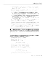
when initialization has been completed, and the console screen displays a script and system
banner similar to the following:
GS Software (GS7), Version 10.3(1)
Copyright (c) 1986-1995 by Cisco Systems, Inc.
Compiled Wed 15-Mar-95 11:06
Step 8
When you start up the router for the first time, the system automatically enters the setup
command facility, which determines which interfaces are installed and prompts you for
configuration information for each one. On the console terminal, after the system displays
the system banner and hardware configuration, you will see the following System
Configuration Dialog prompt:
--- System Configuration Dialog ---
At any point you may enter a questions mark ‘?’ for help.
Refer to the ‘Getting Started’ Guide for additional help.
Default settings are in square brackets ‘[]’. continue with
configuration dialog? [yes]:
You have the option of proceeding with the setup command facility to configure the
interfaces, or exit from setup and use configuration commands to configure global
(system-wide) and interface-specific parameters. You do not have to configure the
interfaces immediately; however, you cannot enable the interfaces or connect them to any
networks until you have configured them.
Many of the interface processor LEDs will not go on until you have configured the interfaces. In
order to verify correct operation of each interface, complete the first-time startup procedures and
configuration, then refer to the LED descriptions in the appendix “Reading LED Indicators” to check
the status of the interfaces.
Your installation is complete. Proceed to the appropriate software configuration publications to
configure your interfaces.
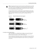
Note
If the system does not complete each of these steps, proceed to the chapter “Troubleshooting
the Installation” for troubleshooting procedures.
Summary of Contents for TelePresence Server 7010
Page 10: ...x Cisco 7010 Hardware Installation and Maintenence ...
Page 14: ...iv Cisco 7010 Hardware Installation and Maintenance Document Conventions ...
Page 148: ...3 36 Cisco 7010 Hardware Installation and Maintenance Using the Flash Memory Card ...
Page 158: ...4 10 Cisco 7010 Hardware Installation and Maintenance Troubleshooting the Processor Subsystem ...
Page 242: ...5 84 Cisco 7010 Hardware Installation and Maintenance Replacing Internal Components ...
Page 258: ...A 16 Cisco 7010 Hardware Installation and Maintenance MIP Interface Cable Pinouts ...
Page 270: ...B 12 Cisco 7010 Hardware Installation and Maintenance Interface Processor LEDs ...
Page 274: ...C 4 Cisco 7000 Hardware Installation and Maintenance ...
Page 287: ...Index 13 ...


