Cisco PA-MC-T3 Installing And Removing Download Page 5

3-5

PA-MC-T3 Port Adapter Installation and Configuration

OL-2695-05

Chapter 3      Removing and Installing Port Adapters

  Port Adapter Removal and Installation

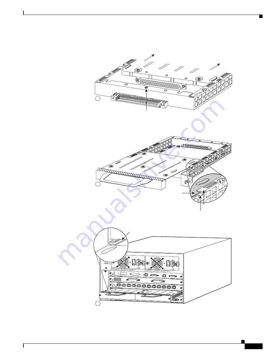
Catalyst RSM/VIP2—Removing and Installing a Port Adapter

Note: You must first remove the 
Catalyst RSM/VIP2 from the chassis 
before removing a port adapter from 
the Catalyst RSM/VIP2.

Step 2

With the screw removed, grasp the 
handle on the front of the
port adapter (or blank port adapter) 
and carefully pull it out of its slot, 
away from the edge connector at 
the rear of the slot. (See A.)

Step 3

To install the port adapter, carefully 
align the port adapter carrier 
between the upper and the lower 
edges of the port adapter slot.
(See B.)

Step 4

Install the screw in the rear of the 
port adapter slot. Do not overtighten 
the screw. (See A.)

Step 6

Reinstall the Catalyst RSM/VIP2 
motherboard in the chassis and 
tighten the captive installation 
screw on each side of the Catalyst 
RSM/VIP2 faceplate. (See C.)

26521

Upper edge

Lower edge

Carrier

A

B

UTP

TX

CHANNEL 1

AUX

CONSOLE

RX

TX

CHANNEL 0

RX

SLO

T 1

RESET

PCMCIA

SLOT 0

CPU HALT

PC

M

IC

A

EJEC

T

STATUS

ROUTE SWITCH MODULE

ENABLED

C

Screw

Step 1

To remove the port adapter, 
remove the screw that secures 
the port adapter (or blank
port adapter). (See A.)

Step 5

Carefully slide the new
port adapter into the port adapter 
slot until the connector on the
port adapter is completely seated in 
the connector at the rear of the
port adapter slot. (See B.)

Slot

guide

Summary of Contents for PA-MC-T3

Page 1: ...ys handle the port adapter by the carrier edges and handle never touch the port adapter components or connector pins See Figure 3 1 Caution Each port adapter circuit board is mounted to a metal carrier and is sensitive to electrostatic discharge ESD damage Warning During this procedure wear grounding wrist straps to avoid ESD damage to the card Do not directly touch the midplane with your hand or ...

Page 2: ...e to gracefully shut down the system before removing a port adapter that has active traffic moving through it Removing a port adapter while traffic is flowing through the ports can cause system disruption Once the port adapter is inserted the ports can be brought back up Caution To prevent system problems do not remove the port adapter from the Catalyst RSM VIP2 Catalyst 6000 family FlexWAN module...

Page 3: ...the port adapter back to their previously installed state Any newly inserted interface is put in the administratively shutdown state as if it was present but not configured at boot time If a similar port adapter type is reinserted into a slot its ports are configured and brought online up to the port count of the originally installed port adapter of that type Note Before you begin installation rea...

Page 4: ...and Installing a Port Adapter page 3 15 Note The PA MC T3 port adapter can be installed in port adapter slots 0 or 1 on the Catalyst RSM VIP2 motherboard the Catalyst 6000 family FlexWAN module or the VIP and in any available port adapter slot in all other systems Caution Each port adapter circuit board is mounted to a metal carrier and is sensitive to electrostatic discharge ESD damage Warning Du...

Page 5: ...d the lower edges of the port adapter slot See B Step 4 Install the screw in the rear of the port adapter slot Do not overtighten the screw See A Step 6 Reinstall the Catalyst RSM VIP2 motherboard in the chassis and tighten the captive installation screw on each side of the Catalyst RSM VIP2 faceplate See C 26521 Upper edge Lower edge Carrier A B UTP TX CH AN NE L 1 AU X CO NS O LE RX TX CH AN NE ...

Page 6: ...ated in the connector at the rear of the port adapter slot See B Slot guide Screw FAN LED 2 3 4 5 6 7 8 9 SUPERVISOR I ST AT US SY ST EM AC TI VE PW R M GM T RE SE T CONSOLE 1 PCMCIA EJECT LI NK LI NK SUPERVISOR I WS X6K SUP1 ST AT US SY ST EM AC TI VE PW R M GM T RE SE T CONSOLE Switch Load 100 1 DTE DCE PCMCIA EJECT PORT 1 LI NK PORT 2 LI NK 8 PORT GIGABIT ETHERNET WS X6408 1 LI N K ST AT US 2 3...

Page 7: ...dapter slot See B Step 6 With the port adapter halfway into the slot connect all required cables to the port adapter After connecting all required cables carefully slide the port adapter all the way into the slot until the port adapter is seated in the router midplane Step 7 After the port adapter is properly seated lock the port adapter lever See A 27996 2 0 4 1 3 5 6 FAST SERIAL EN TD TC RD RC L...

Page 8: ...remains in the unlocked position Place the port adapter lever Cisco uBR7223 see A or the port adapter retention clip Cisco uBR7246 and Cisco uBR7246 VXR see B in the unlocked position Either mechanism remains in the unlocked position Step 2 Grasp the handle of the port adapter and pull the port adapter from the router about halfway out of its slot If you are removing a blank port adapter pull the ...

Page 9: ...ter slot Step 2 Carefully slide the new port adapter halfway into the port adapter slot Step 3 With the port adapter halfway into the slot connect all required cables to the port adapter After connecting all required cables carefully slide the port adapter all the way into the slot until the port adapter is seated in the router midplane Step 4 After the port adapter is properly seated lock the por...

Page 10: ... port adapter lever remains in the unlocked position Step 3 Grasp the handle of the port adapter and pull the port adapter about halfway out of its slot If you are removing a blank port adapter pull the blank port adapter completely out of the chassis slot Step 4 With the port adapter halfway out of the slot disconnect all cables from the port adapter After disconnecting the cables pull the port a...

Page 11: ...halfway out of its slot See B If you are removing a blank port adapter pull the blank port adapter completely out of the chassis slot Step 4 With the port adapter halfway out of the slot diconnect all cables from the port adapter After disconnecting the cables pull the port adapter from its chassis slot Caution The port adapter must slide into the slot guides close to the chassis lid See C Do not ...

Page 12: ...isco 7304 PCI port adapter carrier card before removing a port adapter Step 2 To remove the port adapter from the Cisco 7304 PCI port adapter carrier card turn the port adapter lock from its locked and horizontal position shown in A of Figure 3 2 to its unlocked and vertical position shown in B of Figure 3 2 Step 3 Grasp the handle of the port adapter and pull the port adapter from the Cisco 7304 ...

Page 13: ...2 illustrates how to remove and install a port adapter in a Cisco 7304 PCI port adapter carrier card Figure 3 2 Cisco 7304 PCI Port Adapter Carrier Card Port Adapter Removal and Installation 84657 7300 CC PA OIR STATUS 7300 PA CARRIER ENABLED RXCELLS RXCARRIER RXALARM ATM A C 7300 CC PA OIR STATUS 7300 PA CARRIER B 7300 CC PA ENABLED RXCELLS RXCARRIER RXALARM ATM ...

Page 14: ...r locate the port adapter slot guides inside the Cisco 7401ASR router They are near the top and are recessed about 1 2 inch See B Caution The port adapter must slide into the slot guides under the chassis lid Do not allow the port adapter components to come in contact with the system board or the port adapter could be damaged Step 5 Insert the port adapter in the slot guides halfway and then recon...

Page 15: ...ween the upper and the lower edges of the port adapter slot See B Step 4 Carefully slide the new port adapter into the port adapter slot until the connector on the port adapter is completely seated in the connector at the rear of the port adapter slot See B Step 5 Install the screw in the rear of the port adapter slot on the VIP Do not overtighten the screw See A Step 6 Carefully slide the VIP mot...

Page 16: ...We strongly recommend that you fasten together your transmit and receive cables along their entire length which reduces the effects of EMI You can use standard heat activated shrink tubing or cable ties for this purpose You can also use a 75 ohm coaxial cable pair that is available from Cisco Systems product number CAB ATM DS3 E3 Each T3 link requires separate receive and transmit connections to y...

Page 17: ...ndicated in Step 2 Step 2 Attach the network ends of your two 75 ohm coaxial cables to your external T3 equipment as follows Attach the coaxial cable from the PA MC T3 TX port to the RX port on your external T3 equipment Attach the coaxial cable from the PA MC T3 RX port to the TX port on your external T3 equipment This completes the procedure for attaching 75 ohm coaxial cables to a PA MC T3 Proc...

Page 18: ...3 18 PA MC T3 Port Adapter Installation and Configuration OL 2695 05 Chapter 3 Removing and Installing Port Adapters Connecting a PA MC T3 Cable ...

Reviews: