


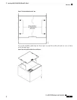


Figure 19: Positioning the Mounting Brackets for Deep Door Configuration
Step 11
Repeat for the other side of the assembly.
Step 12
Return to your originating procedure (NTP).
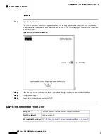
Front Door
The Critical, Major, and Minor alarm LEDs visible through the front door indicate whether a critical, major,
or minor alarm is present anywhere on the ONS 15454 shelf. These LEDs must be visible so that technicians
can quickly determine if any alarms are present on the ONS 15454 shelf or the network. You can use the LCD
to further isolate alarms. The front door as shown in the following figure provides access to the shelf,
fiber-storage tray, fan-tray assembly, and LCD screen.
Cisco ONS 15454 Hardware Installation Guide
45
Installing the ONS 15454 M12 (ANSI and ETSI) Shelf
Front Door
Summary of Contents for ONS 15454
Page 2: ... 2019 Cisco Systems Inc All rights reserved ...
Page 16: ...Cisco ONS 15454 Hardware Installation Guide xvi Contents ...
Page 28: ...Cisco ONS 15454 Hardware Installation Guide xxviii Preface Preface ...
Page 36: ...Cisco ONS 15454 Hardware Installation Guide 6 Overview Cisco ONS 15454 M6 Shelf ...
Page 510: ...Cisco ONS 15454 Hardware Installation Guide 480 Hardware Specifications Dimensions ...