background image

4

Grounding the IC3000

Make sure to follow any grounding requirements at your site. The device must be connected to a reliable earth ground. 
Install the ground wire in accordance with local electrical safety standards. The ground lug is not supplied with the 
device. You can use either a single ring terminal or two single ring terminals.

Note: 

The ground lug is not supplied with the device. You can use either a single ring terminal, two single ring terminals, 

or a double ring terminal.

Warning:


This equipment needs to be grounded.


For NEC-compliant grounding, use size 16 AWG (1.5mm2) or larger 

copper wire and a ring terminal with an inner diameter of 1/4 in. (6 to 7 mm).


Statement 242

Warning: 

T

his equipment must be grounded. Never defeat the ground conductor or operate the equipment in the 

absence of a suitably installed ground conductor. Contact the appropriate electrical inspection authority or an 
electrician if you are uncertain that suitable grounding is available. Statement 1024

Warning: 

When installing or replacing the unit, the ground connection must always be made first and disconnected 

last. Statement 1046

Warning: 

This equipment is intended to be grounded to comply with emission and immunity requirements. Ensure 

that the device functional ground lug is connected to earth ground during normal use. Statement 1064

To ground the IC3000 to earth ground, follow these steps:

Step 1

Use a standard Phillips screwdriver or a ratcheting torque screwdriver with a Phillips head to remove the ground 
screw from the front panel of the device.
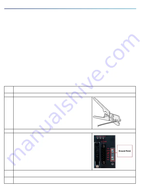
Step 2

Use a wire stripping tool to strip the16 AWG (1.5mm2) grounding wire to 0.22 in. (5.56 mm).

Insert the ground wire into the ring terminal lug, and using a crimping tool, 
crimp the terminal to the wire.

Step 3

Slide the ground screw through the terminal.

Step 4

Insert the ground screw into the functional ground screw opening on the 
front panel.

Attach the ring terminal to the chassis using the screw set aside in step 1.

The graphic to the right shows the proper ground connection points.

Step 5

Use a ratcheting torque screwdriver to tighten the ground screw and ring terminal to the IC3000 front panel to 3.5 
in-lb (0.4 N-m).

Step 6

Attach the other end of the ground wire to a grounded bare metal surface, such as a ground bus, a grounded DIN 
rail, or a grounded bare rack.

332163

Summary of Contents for IC3000

Page 1: ...s on line and subject to change Make sure that you are downloading or viewing on line the latest version before beginning an installation This document also contains Product Compliance and Safety information as well as Declaration of Conformity Related Documentation Installing the IC3000 Grounding the IC3000 Connecting DC Power Connecting to the IC3000 Ports Hazardous Locations Standards and Marki...

Page 2: ... Two Power Connectors Equipment that You Supply For power and alarm connections use UL and CSA rated style 1007 or 1569 twisted pair copper appliance wiring material AWM wire ESD preventive cord and wrist strap Wire crimper for chassis grounding Wire for connecting the chassis to an earth ground Ethernet cables for connecting to the Gigabit Ethernet ports Fiber optic cables and SFP transceivers fo...

Page 3: ...ational electric codes Statement 1074 Warning Explosion Hazard The area must be known to be nonhazardous before installing servicing or replacing the unit Statement 1082 Warning Use twisted pair supply wires suitable for 86 F 30 C above surrounding ambient temperature outside the enclosure Statement 1067 Warning Avoid using or servicing any equipment that has outdoor connections during an electric...

Page 4: ...ways be made first and disconnected last Statement 1046 Warning This equipment is intended to be grounded to comply with emission and immunity requirements Ensure that the device functional ground lug is connected to earth ground during normal use Statement 1064 To ground the IC3000 to earth ground follow these steps Step 1 Use a standard Phillips screwdriver or a ratcheting torque screwdriver wit...

Page 5: ...rning Before performing any of the following procedures ensure that power is removed from the DC circuit Statement 1003 Warning Only trained and qualified personnel should be allowed to install replace or service this equipment Statement 1030 Warning A readily accessible two poled disconnect device must be incorporated in the fixed wiring Statement 1022 To connect DC power Step 1 Locate the power ...

Page 6: ...tcheting torque flathead screwdriver to torque the power connector captive screws above the installed wire leads to 2 in lb 0 23 N m 1 Power connector captive screws Step 8 Connect the other end of the positive wire to the positive terminal on the DC power source and connect the other end of the return wire to the return terminal on the DC power source When you are testing the device one power con...

Page 7: ...entally be turned on or verify that the area is nonhazardous before proceeding Statement 1070 Warning If you connect or disconnect the console cable with power applied to the device or any device on the network an electrical arc can occur This could cause an explosion in hazardous location installations Be sure that power is removed or the area is nonhazardous before proceeding Statement 1080 Conn...

Page 8: ...electrical arc can occur This could cause an explosion in hazardous location installations Be sure that power is removed or the area is nonhazardous before proceeding Statement 379 Caution Use a ratcheting torque flathead screwdriver to torque the power connector captive screws to 5 in lb 0 6 N m the maximum recommended torque Hazardous Locations Standards and Marking Strings The following standar...

Page 9: ...onger complying with FCC requirements for Class A digital devices In that event your right to use the equipment may be limited by FCC regulations and you may be required to correct any interference to radio or television communications at your own expense This equipment has been tested and found to comply with the limits for a Class A digital device pursuant to Part 15 of the FCC Rules These limit...

Page 10: ...10 This page left intentionally blank ...

Page 11: ...11 This page left intentionally blank ...

Page 12: ...s of Cisco and or its affiliates in the U S and other countries To view a list of Cisco trademarks go to this URL www cisco com go trademarks Third party trademarks mentioned are the property of their respective owners The use of the word partner does not imply a partnership relationship between Cisco and any other company 1721R 2018 Cisco Systems Inc All rights reserved ...

Reviews: