D9824 Receiver Rear Connector Panel
23
D9824 Receiver Rear Connector Panel
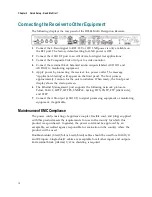
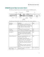
The following diagram shows the rear connector panel of the D9824 receiver:
The following table describes the function and type of the various connectors.
Connector
Description
Type
RF Inputs
Each input accepts an LNB signal input.
RF1 provides LNB power for use when no
external LNB power source is available. RF2
to RF4 require an external LNB power
source.
F
ASI Input
Asynchronous Serial Interface Input.
BNC
ASI Output
One Asynchronous Serial Interface Output. BNC
Management
Supports the following network protocols:
Telnet, SSHv2, HTTP, HTTPS, SNMPv2,
Syslog/DTX, SNTP, FTP (client side), and
TFTP.
RJ-45
TS Inputs/Outputs (2)
These are for the MPEGoIP Inputs, and
MPEGoIP and MPE outputs.
The MPEGoIP output transmits the
decrypted transport stream encapsulated in
IP packets to a groomer for distribution.
The MPE output receives and outputs the IP
data packets from the incoming transport
stream.
The MPEGoIP input allows the decoder to
receive its streams from the terrestrial IP
network.
RJ-45
Cue Tone/Cue Trigger
Relay Outputs
Program relay provides programmed
responses for alarms.
15-pin sub-D female
Summary of Contents for D9824
Page 22: ......
Page 26: ...Chapter 1 Introduction 4 On Screen Display support on baseband output NIT Retune Recovery ...
Page 40: ......
Page 164: ......
Page 306: ......
Page 368: ......
Page 370: ......
Page 388: ......
Page 410: ...Appendix C Compliance 388 Declarationof Conformity ...
Page 415: ......

