


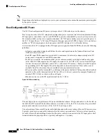


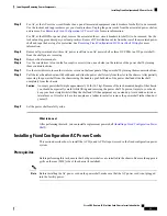


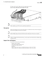


Figure 18: Input-Power-Present LEDs—Modular Configuration DC Power Shown
The input-power-present LED starts to light up when the input voltage reaches –20 VDC and the LED gets
brighter as voltage increases; the input-power-present LED is fully lit when the input voltage reaches –38
VDC.
If the input voltage polarity is reversed, or if the LED circuit fails, the LED will not light. When this is the
case, service personnel should check for hazardous voltages before working on the unit.
Caution
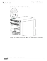
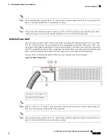
AC Power Systems
Each AC powered chassis contains two AC power shelves for 2N redundancy. The shelves contain the input
power connectors.
• In the fixed configuration power system, each shelf contains three AC power rectifiers. The power shelves
and AC power rectifiers are field replaceable. Each shelf and AC power rectifier has its own circuit
breaker.
• In the modular configuration power system, each shelf can contain up to six AC PMs. The power shelves
and the AC PMs are field replaceable.
Depending on the hardware deployed at your site, your system may not consume the maximum power supplied
by the power system.
Note
Cisco CRS Routers 16-Slot Line Card Chassis Installation Guide
27
Installing and Removing Power Components
AC Power Systems


