


Understanding the Alphanumeric LEDs
On the card front panel, the RP, PRP, or DRP card has an alphanumeric LED display that shows a sequence
of messages indicating the state of the card.
It is normal for some displayed messages to appear too briefly in the LED display to be read.
Note
Troubleshooting the RP, PRP, or DRP Card
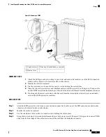
If the installed or replaced card fails to operate or to power up on installation:
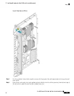
• Make sure that the card is seated firmly in the LCC slot. One easy way to verify physical installation is
to see whether the front faceplate of the card is even with the fronts of the other cards installed in the
card cage.
PRP cards only—If the PRP is not seated properly, the blue OIR Ready LED on the faceplate glows solidly,
and the PRIMARY and STATUS LEDs keep blinking to indicate that the card is not seated correctly. If this
happens, remove the card fully and re-insert fully.
Note
• Check whether the ejector levers are latched and that the captive screws are fastened properly. If you are
uncertain, unlatch the levers, loosen the screws, and attempt to reseat the card.
• Examine the alarm module to see if there are any active alarm conditions. See
System 16-Slot Line Card Chassis System Description
for information on the alarm module.
• Examine the power shelves to see whether the chassis, as a whole, is receiving power.
Use the card status LED, located on the RP and PRP card front panel, to verify the correct installation of the
card:
• When the card is properly installed, the card status LED turns green. If this LED is off, verify that the
card is installed correctly.
• When the card status LED is blinking yellow, a problem exists on the board.
• When the card status LED is off, the board status is unknown. Verify that there is power to the board by
looking at the indicators on the power shelf.
• If a failure occurs during the board boot sequence, the four-digit alphanumeric display indicates the
current boot phase to assist you in debugging the board failure.
Installing or Removing a PLIM
This section contains the following procedures:
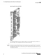
Some PLIMs contain Class 1 lasers, while others contain Class 1M lasers; for details of your PLIM, see the
Cisco CRS Carrier Routing System 16-Slot Line Card Chassis System Description
.
Note
Cisco CRS Routers 16-Slot Line Card Chassis Installation Guide
153
Installing and Removing Line Cards, PLIMs, and Associated Components
Understanding the Alphanumeric LEDs


