


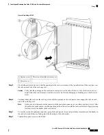

• Examine the power shelves to see whether the chassis, as a whole, is receiving power.
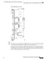
Use the Status LED, located on the LCC fan controller card faceplate, to verify the correct installation of the
card:
• When the card is properly installed, the Status LED turns green. If this LED is off, verify that the card
is installed correctly.
• When the Status LED is blinking yellow, a problem exists on the board.
• When the Status LED is off, the board status is unknown. Verify that there is power to the board by
looking at the indicators on the power shelf.
• If a failure occurs during the board boot sequence, the two four-digit alphanumeric display indicate the
current boot phase to assist you in debugging the board failure.
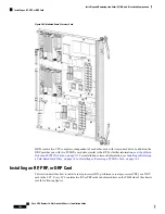
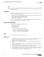
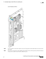
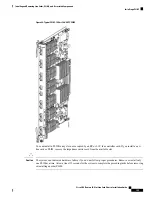
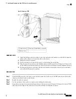
Installing or Removing an RP, PRP, or DRP PLIM
This section contains the following topics:
Class 1 Laser Product. Statement 113
Warning
Because invisible radiation may be emitted from the aperture of the port when no fiber cable is connected,
avoid exposure to radiation and do not stare into open apertures. Statement 125
Warning
About Distributed Route Processors and Distributed Route Processor PLIMs
The Cisco CRS Carrier Routing System provides distributed route processor (DRP) support through the
installation of DRP PLIMs and DRP cards on the LCC . The installation of DRPs provides you with the ability
to configure the system for logical router support and additional processor power for multichassis systems.
Cisco CRS Routers 16-Slot Line Card Chassis Installation Guide
144
Installing and Removing Line Cards, PLIMs, and Associated Components
Installing or Removing an RP, PRP, or DRP PLIM


