background image

• Keep the work area clear, smoke and dust-free during and after installation. Do not allow dirt or debris

to enter into any laser-based components.

• Do not wear loose clothing, jewelry, or other items that could get caught in the router or other associated

components.

• Cisco equipment operates safely when used in accordance with its specifications and product-usage

instructions.

• Be sure to power down a fixed configuration PDU or modular configuration power shelf before removing

it from the chassis.

• If potentially hazardous conditions exist, do not work alone.

• Take care when connecting multiple units to the supply circuit so that wiring is not overloaded.

• This equipment must be grounded. Never defeat the ground conductor or operate the equipment in the

absence of a suitably installed ground conductor. Contact the appropriate electrical inspection authority
or an electrician if you are uncertain about whether suitable grounding is available.

• When installing or replacing the unit, the ground connection must always be made first and disconnected

last.

• To prevent personal injury or damage to the chassis, never attempt to lift or tilt the chassis using the

handles on modules (such as power supplies, fans, or cards); these types of handles are not designed to
support the weight of the unit.

• Hazardous voltage or energy is present on the backplane when the system is operating. Use caution when

servicing.

• The rack stabilizing mechanism must be in place, or the rack must be bolted to the floor before you slide

out the unit for servicing. Failure to stabilize the rack may cause the rack to tip over.

Compliance and Safety Information

The Cisco 8000 Series Routers are designed to meet the regulatory compliance and safety approval requirements.
For detailed safety information, see

Regulatory Compliance and Safety Information—Cisco 8000 Series

Routers

.

Laser Safety

Statement 1051—

Laser Radiation

Invisible laser radiation may be emitted from disconnected fibers or connectors. Do not stare into beams or
view directly with optical instruments.

Warning

Prepare for Installation

2

Prepare for Installation

Compliance and Safety Information

Summary of Contents for 8000 Series

Page 1: ...device SAVE THESE INSTRUCTIONS Warning Safety Guidelines on page 1 Compliance and Safety Information on page 2 Laser Safety on page 2 Energy Hazard on page 3 Preventing Electrostatic Discharge Damage on page 3 Cautions and Regulatory Compliance Statements for NEBS on page 4 Installation Guidelines on page 4 Procure Tools and Equipment on page 5 Prepare Your Location on page 7 Prepare Yourself on p...

Page 2: ...placing the unit the ground connection must always be made first and disconnected last To prevent personal injury or damage to the chassis never attempt to lift or tilt the chassis using the handles on modules such as power supplies fans or cards these types of handles are not designed to support the weight of the unit Hazardous voltage or energy is present on the backplane when the system is oper...

Page 3: ...minals Always replace cover when terminals are not in service Be sure uninsulated conductors are not accessible when cover is in place Warning Preventing Electrostatic Discharge Damage Many router components can be damaged by static electricity Not exercising the proper electrostatic discharge ESD precautions can result in intermittent or complete component failures To minimize the potential for E...

Page 4: ...t shall be connected to AC mains provided with a surge protective device SPD at the service equipment complying with NFPA 70 the National Electrical Code NEC Statement 7012 Warning This equipment is suitable for installations utilizing the Common Bonding Network CBN Statement 7013 Warning The battery return conductor of this equipment shall be treated as DC I Statement 7016 Warning This equipment ...

Page 5: ...uirements see Cisco 8000 Series Routers Data Sheet Note When the Cisco 8200 Series Routers use port side exhaust fans and power supplies the maximum temperature is reduced by 5 degrees C for example 35 degrees C at sea level or 30 degrees C at 1500 meters Note Procure Tools and Equipment Obtain these necessary tools and equipment for installing the chassis Number 1 and number 2 Phillips screwdrive...

Page 6: ...s in your kit such as documentation hardware and power cables The shipped cables depend on your specification when placing an order See the Power Supply Power Cord Specifications section for information on the available power cords If you notice any discrepancies or damage send the following information to your customer service representative by email Invoice number of the shipper see the packing ...

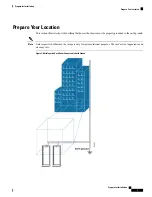
Page 7: ...properly grounded to the earth ground Unless specified otherwise the image is only for representational purposes The rack s actual appearance and size may vary Note Figure 1 Building with Rack Room Connected to Earth Ground Prepare for Installation 7 Prepare for Installation Prepare Your Location ...

Page 8: ...ck for Chassis Installation Install the Cisco 8800 Series Routers on a standard 19 inch Electronic Industries Alliance EIA rack with mounting rails that conform to English universal hole spacing according to Section 1 of the ANSI EIA 310 D 1992 standard The spacing between the posts of the rack must be EIA 310 D 1992 19 inch rack compatible wide enough to accommodate the width of the chassis Befor...

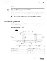
Page 9: ...f bolts is required Ensure that the rack in which the chassis is being installed is grounded to earth ground Note Clearance Requirements To ensure adequate airflow we recommended that you maintain a minimum clearance distance always as mentioned in the following figure Following figure shows the clearances required for installation of Cisco 8800 Series Routers Figure 3 Clearances Required Around t...

Page 10: ... fabric card replacement Following figure shows the clearances required for the cable management of Cisco 8800 Series Routers Figure 4 Clearances Required Around the Chassis Door 3 Depth of cable management 1 Overall door width on side in an open position 4 Overall door depth on front in an open position 2 Maximum vertical rack rail setback when filters are installed on the chassis Prepare for Ins...

Reviews: