background image


Printed in the USA on recycled paper containing 10% postconsumer waste.

78-21441-03

Americas Headquarters

Cisco Systems, Inc.

San Jose, CA

Asia Pacific Headquarters

Cisco Systems (USA) Pte. Ltd.

Singapore

Europe Headquarters

Cisco Systems International BV Amsterdam, 

The Netherlands

Cisco has more than 200 offices worldwide. Addresses, phone numbers, and fax numbers are listed on 

the Cisco Website at

www.cisco.com/go/offices

.

Summary of Contents for 7330

Page 1: ...QUICK START GUIDE Cisco Universal Small Cell 7330 ...

Page 2: ... Your Small Cell Mounting on a Wall or Hard Ceiling Mounting on a Suspended Ceiling Mounting on a Suspended Ceiling Using an Existing Bracket Mounting in a Plenum Space 6 Verify that Your Small Cell is Operating Correctly 7 Declarations of Conformity and Regulatory Information 8 Specifications 9 Obtaining Documentation and Submitting a Service Request ...

Page 3: ...neration 3G users and supports Band 2 5 for the American market and Band 1 for the rest of the world Package Contents Your Cisco USC 7330 small cell is shipped with the following Power supply unit European Union EU compatible type plug for Band 1 and US compatible plug for Band 2 5 Other plug types must be ordered separately Suspended ceiling mount bracket to mount the small cell on a ceiling Rail...

Page 4: ...4 Figure 1 Cisco USC 7330 Top View 1 Power LED 2 Ethernet connection LED 3 Status LED 4 External antenna port 361429 2 3 1 4 ...

Page 5: ...low your small cell to provide the best possible coverage at least one 30 cm 1 foot from other wireless broadcasting devices to avoid possible interference where you can connect to your broadband router or cable modem Decide whether you will mount your small cell on a wall or ceiling or whether you will place it on a desktop or other flat surface ...

Page 6: ...uld cause bodily injury Before you work on any equipment be aware of the hazards involved with electrical circuitry and be familiar with standard practices for preventing accidents Use the statement number provided at the end of each warning to locate its translation in the translated safety warnings that accompanied this device Statement 1071 SAVE THESE INSTRUCTIONS Warning Read the installation ...

Page 7: ...rotective device is rated not greater than 20A Statement 1005 Warning Do not operate the unit near unshielded blasting caps or in an explosive environment unless the device has been modified to be especially qualified for such use Statement 364 Warning In order to comply with FCC radio frequency RF exposure limits antennas should be located at a minimum of 7 9 inches 20 cm or more from the body of...

Page 8: ...indoors within the same building including the associated LAN connections as defined by Environment A of the IEEE 802 af Standard Note Your small cell is suitable for use in environmental air space in accordance with section 300 22 C of the National Electrical Code and sections 2 128 12 010 3 and 12 100 of the Canadian Electrical Code Part 1 C22 1 You should not install the power supply or power i...

Page 9: ...9 4 Connect Your Small Cell Figure 2 Cisco USC 7330 Connections 1 10 100 Base T Ethernet port supporting PoE 2 Power port 3 GPS port available on Band 2 5 only 6 361430 1 2 3 4 5 ...

Page 10: ...nnect an external antenna for the Sniff bands Bands 3 and 8 to connector 5 and connect the external antenna for Band 1 to connector 6 Figure 2 For the USC7330 T2 K9 connect an external antenna for Band 5 to connector 5 and connect the external antenna for Band 2 to connector 6 Figure 2 4 Reset button 5 2G external antenna port for the Band 1 small cell USC7330 T1 K9 or UMTS Band V external antenna...

Page 11: ...is ready to use 5 Mount Your Small Cell Mounting on a Wall or Hard Ceiling If you need to mount your small cell on a wall or hard ceiling hang it on two screws projecting from the surface Attach the screws to the wall or ceiling such that the distance between the screws matches the distance between the mounting holes on the back of your small cell ...

Page 12: ...12 Figure 3 Cisco USC 7330 Mounted Vertically on Wall 380785 ...

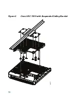
Page 13: ...it and screw them into each of the two corresponding holes on the bottom of the small cell Step 3 Attach the suspended ceiling bracket to the ceiling rail system using the two L brackets included in the accessory pack and eight screws Step 4 Place the small cell such that the attached mounting screws fit into the suspended ceiling bracket keyhole mounting slots Step 5 Slide the small cell onto the...

Page 14: ...14 Figure 4 Cisco USC 7330 with Suspended Ceiling Bracket 381277 ...

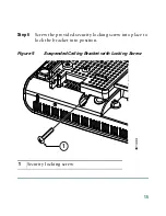
Page 15: ...15 Step 6 Screw the provided security locking screw into place to lock the bracket into position Figure 5 Suspended Ceiling Bracket with Locking Screw 1 Security locking screw 1 361433 ...

Page 16: ... to use for your Cisco USC 7330 perform this task Step 1 Connect the suspended ceiling bracket to your small cell as described in Mounting on a Suspended Ceiling page 13 perform Step 1 Step 2 and Step 4 to Step 6 Step 2 Screw the four metal feet into the four corresponding holes on the bottom of the suspended ceiling bracket The rubber feet attachments are not required ...

Page 17: ...ket AIR AP BRACKET 1 as described in Access Point Mounting Instructions http www cisco com en US partner docs wireless access_point mounting guide apmount html Step 4 Fasten a padlock to secure the small cell to the brackets and prevent theft See Securing the Access Point to the Mounting Plate for more information 361434 ...

Page 18: ...18 Figure 7 Cisco USC 7330 with Padlock Attached 1 Padlock 361436 1 ...

Page 19: ...6 2 Connect your small cell to the suspended ceiling bracket as described in Mounting on a Suspended Ceiling Using an Existing Bracket Then connect this to another bracket as described in Access Point Mounting Instructions http www cisco com en US partner docs wireless access_point mounting guide apmount html 6 Verify that Your Small Cell is Operating Correctly The LED display is located on the fr...

Page 20: ...No connection to local broadband router verify the connection between the broadband router and your small cell and verify that the broadband router is operational Red Flash 2 times in 4 seconds No Internet connection verify that the broadband router is connected to the Internet and is providing service Red Flash 3 times in 4 seconds Interference with other systems try placing your small cell in a ...

Page 21: ... Initial boot wait up to 20 minutes if the state does not change perform a reset Cannot create secure connection contact customer support Internal fault small cell has a fault and cannot provide service RF issue cannot select an RF profile verify whether another small cell is located in close proximity and if so relocate the unit Provisioning failure contact customer support Table 1 USC 7330 Statu...

Page 22: ...s been tested and found to comply with the limits for a Class B digital device pursuant to Part 15 of the FCC Rules These limits are designed to provide reasonable protection against harmful interference in a residential installation This equipment generates uses and can radiate radio frequency energy and if not installed and used in accordance with the instructions may cause harmful interference ...

Page 23: ...ipment into an outlet on a circuit different from that to which the receiver is connected Consult the dealer or an experienced radio TV technician for help Declaration of Conformity Statements All the Declaration of Conformity statements related to this product can be found at the following URL http www ciscofax com 8 Specifications Product numbers USC7330 T1 K9 Band 1 USC7330 T2 K9 Band 2 5 3GPP ...

Page 24: ... 900 EU Band II 1900 and Band V 850 US Maximum transmit power UMTS 24 dBm energy consumption 12 Watt Sensitivity 113 dBm UL sensitivity compliant to 3GPP TS25 104 Embedded 3G and GSM omnidirectional antennas USC7330 T2 K9 GPS with external GPS antenna connector Dimensions L x W x D 7 20 x 7 17 x 1 50 inches 18 3 x 18 2 x 3 8 cm Weight USC7330 T1 K9 1 19 lbs 540 g USC7330 T2 K9 1 21 lbs 550 g Opera...

Page 25: ... Antenna Requirements Before attaching an external antenna to your small cell note the following requirements Table 2 UMTS Antenna Requirements Gain 0 dBi mean 2 dBi peak Ripple 2 dB Azimuth Beamwidth Omni Elevation Beamwidth Omni Isolation UMTS to GSM listen UMTS to WLAN 15 dB 15 dB Feed System Coaxial feed Return loss 10 dB over band specified Power rating 24 dBm ...

Page 26: ...mwidth Omni Elevation Beamwidth Omni or similar to vertical mounted dipole nulls at θ 0 and 180 degrees are acceptable Isolation GSM to UMTS listen GSM to WLAN 15 dB 15 dB Feed System Coaxial feed Return loss 6 dB over band specified Power rating 0 dBm Polarization Linear Connector type MMCX 50 Ohm Table 2 UMTS Antenna Requirements continued ...

Page 27: ...ring additional information see the monthly What s New in Cisco Product Documentation which also lists all new and revised Cisco technical documentation http www cisco com en US docs general whatsnew whatsnew html Subscribe to the What s New in Cisco Product Documentation as an RSS feed and set content to be delivered directly to your desktop using a reader application The RSS feeds are a free ser...

Page 28: ...sco Systems Inc San Jose CA Asia Pacific Headquarters Cisco Systems USA Pte Ltd Singapore Europe Headquarters Cisco Systems International BV Amsterdam The Netherlands Cisco has more than 200 offices worldwide Addresses phone numbers and fax numbers are listed on the Cisco Website at www cisco com go offices ...

Reviews: