


© Copyright 2007 Cisco Systems, Inc.
This document may be freely reproduced and distributed whole and intact including this Copyright Notice.
11
Solid Orange
AIM0 installed and initialized error
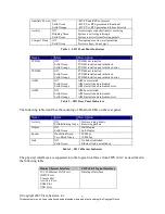
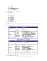
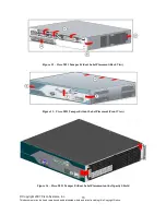
Table 6 – 2821 Rear Panel Indicators
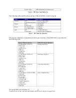
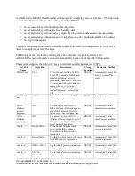
The following table describes the meaning of Ethernet LEDs on the front panel:
Name
State
Description
Activity
Off
Solid/Blinking Green
Not receiving packets
Receiving packets
Duplex
Off
Solid Green
Half-Duplex
Full-Duplex
Speed
One Blink Green
Two Blink Green
10 Mbps
100 Mbps
Link
Off
Solid Green
No link established
Ethernet link is established
Table 7 – 2821 Ethernet Indicators
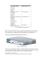
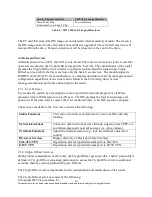
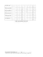
The physical interfaces are separated into the logical interfaces from FIPS 140-2 as described in
the following table:
Router Physical Interface
FIPS 140-2 Logical Interface
10/100 Ethernet LAN Ports
HWIC Ports
Console Port
Auxiliary Port
ENM Slot
VeNoM Slot
USB Ports
Data Input Interface
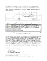
10/100 Ethernet LAN Ports
HWIC Ports
Console Port
Auxiliary Port
ENM Slot
VeNoM Slot
USB Ports
Data Output Interface
10/100 Ethernet LAN Ports
HWIC Ports
Power Switch
Console Port
Auxiliary Port
ENM Slot
Control Input Interface
10/100 Ethernet LAN Port LEDs
AIM LEDs
PVDM LEDs
Power LED
Activity LEDs
Auxiliary LED
Compact Flash LED
Console Port
Auxiliary Port
USB Ports
Status Output Interface