background image

CR:270 Series User Manual 


Page 24 

Specification 


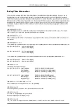
The range of measurement for Leq and SPL measurement with a standard assembly is:- 
 

CR:272 & CR:274   

32 to 140 dB(A) 


50 to 140 dB(C) 


CR:271 & CR:273   

27 to 140dB(A) 


47 to 140dB(C) 

 
The range of measurement for Peak measurement with a standard assembly is:- 


CR:272 & CR:274   

60 to 143 dB(C) 


CR:271 & CR:273   

60 to 143dB(C) 


Noise:  


Signal to noise ratio normally better than 5dB at lower limit of 

capsule sensitivity for quoted range typically 1microV(A) 8uv (C) 
 

Input impedance:   

Typically 1 Gigohm 


Weighting networks: 

'A' and 'C' for CR:272 and CR:271 


'A' and 'Lin' for CR:274 & CR:273 


Display type  


3½ digit reflective LCD 


Time weighting: 


S (Slow) ; F (Fast) ; I (Impulse) 


All to IEC 651 relevant Type 


Display functions   

Average Sound Level 

Leq 


Sound Level  


SPL 


True Peak   


Peak 


Max hold (S, F and I) 


Octave Band Filter Selected for CR:274 & CR:273   

Display flags  

Overload (+) 


Under-range (-) 


Battery Low (BATT LOW) 


Leq Full (:) 


Power: 


2 x 9V batteries 6F22 (40hr) 


Operating Temperature  -10 degrees C to +50 degrees C 

Storage Temperature: 

-20 degrees C to +60 degrees C 


Dimensions: Length  

230mm for CR:272 & CR:274 


255mm for CR:271 & CR:273 


Width  75mm  


Depth  

25mm 


Weight: 


0.5kg 


Output: 


3.5mm 'Stereo jack socket' 


DC out on tip, 25 mV /dB 


AC out on ring.

Summary of Contents for CR:270 Series

Page 1: ...CR 270 Series User Manual Page 1 CR 270 Series Sound Level Meters User Manual This manual the software to which it relates the program code and drawings are all Copyright Cirrus Research plc 1989 2015...

Page 2: ...plc No liability is accepted for any inaccuracies or omissions in this manual although due care has been taken to ensure that is it complete and accurate as possible Accessories supplied by Cirrus Re...

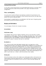
Page 3: ...0 Selecting the Active filter 10 Turning off Octave filters 11 Filters and Weighting 11 Display and Indicators 11 Annunciators 11 Full Centre colon 11 Overload 11 Battery low 11 Summary 12 Calibration...

Page 4: ...eting both these specifications to Type 1 and Type 2 accuracy where applicable The CR 273 and CR 274 instruments also features octave band filters that meet or exceed the requirements of IEC 1260 The...

Page 5: ...t Switches for Calibration Calibrate Instrument Check Battery Select Function Check Range Reset Sound Level SPL Average Sound Level Leq Peak Level LPeak C Record Measurement Check Calibration Power Of...

Page 6: ...sure that the black HOLD button is OUT If this is not done the display will not freeze the last reading and the central colon will be displayed in the LCD Always check the instrument calibration befor...

Page 7: ...ll be reset by the instrument to prevent nonsensical results due to mixtures of levels or weightings The centre position marked dB C permits use as a normal sound level meter with the C Weighting filt...

Page 8: ...he right hand position SPL and in the left hand position it will measure Leq The position of the switch does NOT affect the acquisition of data by the Leq circuitry the switch simply determines what i...

Page 9: ...ALL accidently In the Leq mode the button does NOT cause the reading to go to zero While RESET ALL is pressed the reading will be in an undefined random position as the meter is trying to divide two...

Page 10: ...e upper most label will all be extinguished Switching on the filters One quick push duration less than 1 second of the OCTAVE FILTER button will switch in the octave filters ie make them active Once t...

Page 11: ...is simply that data acquisition stops The CR 27x will still function on SPL and PEAK C If this colon lights then read the Leq note it along with the peak if required and reset the instrument Overload...

Page 12: ...rument more internationally compatible Summary Function Annunciator Cause Possible Action Overload Amplifier overload Move UP one range Under range Amplifier at noise floor Move DOWN one range Battery...

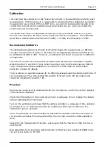
Page 13: ...psule whilst the CR 271 and CR 273 instrument are fitted with the MK 224 capsule Both of these microphones have a calibration correction of 0 3dB Refer to the Acoustic Calibrator manual for details Th...

Page 14: ...th Cirrus Research As A and C weightings all have nominal zero correction loss at 1kHz the reading on these two positions should be nominally the same However due to minor instrument tolerances there...

Page 15: ...ll the battery leads The batteries are connected to clips which are designed to prevent the batteries from being connected with the wrong polarity Types of batteries The CR 270 series should be used w...

Page 16: ...sses involved and the order in which these should be applied if appropriate Octave Band Method The Octave band method is a straightforward noise reduction calculation involving the measurement of the...

Page 17: ...s from the octave band sound pressure levels Octave Band Centre Frequency Hz 63 125 250 500 1000 2000 4000 8000 SPL APV 7 4 10 0 14 4 19 6 22 8 29 6 38 8 34 1 To calculate the effective A Weighted so...

Page 18: ...predicted noise level reduction PNR is calculated from the H M and L values The formula used depends upon the difference between the LCeq and the LAeq If LCeq LAeq is less than or equal to 2 2 4 A C...

Page 19: ...ncidence is parallel to the case as marked with an arrow on the cone IEC 804 651 11 2 3 The range of measurement for Leq and SPL measurement with a standard assembly is CR 272 CR 274 32 to 140 dB A 50...

Page 20: ...on for a microphone extension cable on the standard CR 272 CR 274 units However if an extension cable option is in use with the CR 271 or CR 273 units C irrus Research cables up to 10 meters long will...

Page 21: ...ld use IEC 804 11 2 28 The indicator range is identical to the linearity range of IEC 804 11 2 4 Additional Octave information The CR 274 meets IEC 1260 Type 2 whilst the CR 273 meets IEC 1260 Type 1...

Page 22: ...74 60 to 110dB 0 5dB CR 273 50 to 110dB 0 5dB IEC 1260 7j The range should be selected such that neither the underrange or overload flags occur during measurement IEC 1260 7k Not applicable IEC 1260 7...

Page 23: ...CD display battery annunciator indicates that the batteries are not sufficient to run the instrument correctly IEC 1260 7t The filter is integral to the CR 273 and CR 274 IEC 1260 7u The instrument is...

Page 24: ...ally 1 Gigohm Weighting networks A and C for CR 272 and CR 271 A and Lin for CR 274 CR 273 Display type 3 digit reflective LCD Time weighting S Slow F Fast I Impulse All to IEC 651 relevant Type Displ...

Page 25: ...after 1st January 1996 CR 272 Sound Level Meter CR 271 Sound Level Meter CR 274 Sound Level Meter CR 273 Sound Level Meter Along with their standard accessories According to EMC Directives 89 336 EEC...

Page 26: ...will be a reduced charge for their replacement during the annual Traceable Calibration 8 On completion of the annual Traceable Calibration by Cirrus Research plc or an official Cirrus Calibration Cent...

Page 27: ...manby North Yorkshire United Kingdom YO14 0PH Telephone 44 0 1723 891655 Fax 44 0 1723 891742 E mail sales cirrusresearch co uk Web Site www cirrusresearch co uk Germany Cirrus Research plc Deutschlan...

Reviews: