DS726PP2
53
CS4525
6.1.11
Interrupt Reporting
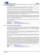
The CS4525 has comprehensive interrupt reporting capabilities. Many conditions including SRC lock,
ADC overflow, digital data path overflow, and amplifier errors can cause an interrupt.
The INT output pin is intended to drive an interrupt input pin on a host microcontroller. The INT pin is an
open-drain active-low output and requires an external pull-up for proper operation.
If an interrupt source is un-masked, its occurrence will cause the interrupt output pin to become active. To
enhance flexibility, each interrupt source may be masked such that its occurrence does not cause the in-
terrupt output pin to become active. This masking function is accomplished by clearing an interrupt’s re-
spective mask bit located in the 4 LSB’s of the Interrupt register.
When a specific interrupt condition occurs, it’s respective bit located in the 4 MSB’s of the Interrupt register
will be set to indicate that a change has occurred for the associated interrupt type. When the interrupt reg-
ister is read, the contents of the 4 MSB’s will be cleared. The Int Status register may then be read to de-
termine the current state of the interrupt source.
For specific information regarding interrupt types and reporting, see the Interrupt, Int Status and Amp Er-
ror register descriptions.
6.1.12
Automatic Power Stage Shut-Down
To prevent permanent damage, the CS4525 will automatically shut down its internal PWM power output
stages when a thermal error, PWM power output over-current error, or VP under-voltage condition occurs.
In the shut-down state, all digital functions of the device will operate as normal, however the PWM power
output pins become high-impedance.
The levels of the over-current error, thermal error, and VP under-voltage trigger points are listed in the
PWM Power Output Characteristics
table on
. Automatic shut-down will occur whenever any of
these preset thresholds are crossed.
Once in the shut-down state, each powered PWM outputs will remain as high-impedance and will not re-
sume normal operation until either the PDnAll bit or the PDnOutX bit for the channel in error is set and
then cleared.
If the AutoRetry bit is set, the CS4525 will attempt to automatically resume power output operation after
an over-current error is encountered and before entering the shut-down state. With the AutoRetry function
enabled, the CS4525 will place the PWM power outputs in a high-impedance state upon the sensing of
an over-current condition, wait approximately 85 ms, and then re-engage the power outputs in an attempt
to resume normal operation. If another over-current condition is immediately detected, the PWM power
outputs will again be placed in a high-impedance state before retrying to resume normal operation a sec-
ond time. It will continue this sequence for a maximum of five attempts. After the fifth unsuccessful at-
tempt, the outputs will remain in a high-impedance state until the PDnAll bit is set and then cleared.
Referenced Control
Register Location
Interrupt Register ................
“Interrupt (Address 60h)” on page 89
Int Status Register...............
“Interrupt Status (Address 61h) - Read Only” on page 92
Amp Error Register .............
“Amplifier Error Status (Address 62h) - Read Only” on page 93
Referenced Control
Register Location
AutoRetry ............................
“Automatic Power Stage Retry (AutoRetry)” on page 88
PDnAll .................................
“Power Down (PDnAll)” on page 89
PDnOutX .............................

