background image

Section 5: Test Your First Cable / Print or transcribe an error list

1000R+ User’s Guide / page 28

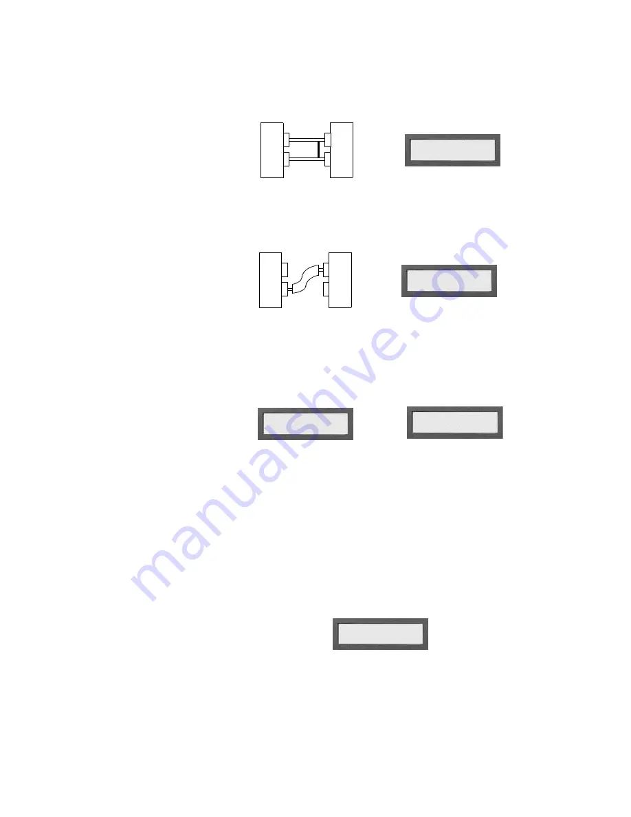
If the analyzer detects a short:

The display prompts 

Short Detected

, and the analyzer emits a series of double 

beeps.

If both opens and shorts are detected:

The display prompts 

Errors Detected

, and the analyzer emits a series of triple 

beeps.

If an insulation short is detected:
The display prompts either 

Bad R> X

s or 

Insulation Short

.  Both prompts indi-

cate that the measured resistance is higher than the Connection Resistance setting, 
and lower than the Insulation Resistance setting.  The analyzer emits a series of dou-
ble beeps.

Intermittent

If a cable develops shorts or opens after it first tests as good, the display prompts an 
intermittent error.  The analyzer emits a steady series of clicks as though the cable 
were good.  

Press 

Display/Print

 to show the error condition that existed when the 

intermittent occurred.  

Clear the intermittent by pressing the 

Memory

 button on the back of the 

analyzer.

Print or transcribe an

error list

If the analyzer detects errors, it can prompt where the error is in a cable.  To do this, 
press 

Display/Print

 while the cable is still connected to the analyzer.  If you have a 

printer connected to your analyzer, it will automatically print out an error list.  If you 
don’t have a printer, keep pressing 

Display/Print

 to step through the errors as you 

transcribe them to a cable documentation form (see page 79).

SHORT DETECTED
 

ERRORS DETECTED
 

BAD R>.x


or

INSULATION SHORT
 

SIG:XXXXXX-XXXX
 INTERMITTENT

Summary of Contents for Signature 1000R+

Page 1: ...Signature 1000R Cable Analyzer User s Guide Version 4 0 Major Revision 23 September 1999...

Page 2: ...s Guide Version 4 0 Major Revision 23 September 1999 Copyright 1999 by Cirris Systems Corporation 1991 Parkway Boulevard Salt Lake City Utah 84119 2026 United States of America All rights reserved Vi...

Page 3: ......

Page 4: ...on 5 Test Your First Cable 27 Section 6 Retrieve a Cable from Memory 29 Section 7 Delete a Cable from Memory 31 Section 8 Print a Directory of Cables Stored in Memory 33 Section 9 Cable Documentation...

Page 5: ...1000R User s Guide page 6...

Page 6: ...data for the kind of cable you want to test from the analyzer s memory see page 29 for details This completes programming the analyzer for testing cables If you have connected a Sample Cable to learn...

Page 7: ...Introduction to the Cirris 1000R What your order should contain 1000R User s Guide page 8...

Page 8: ...connector adapters To install connector adapters onto the Cirris 1000R follow these steps 1 Turn the four twistlock fasteners on the adapter cover plate to unlock them and remove the cover plate 2 Plu...

Page 9: ...to install an expansion box Up to three expansion boxes can be installed on your 1000R to increase the number of test points available You can set up your system to have as many as 512 test points To...

Page 10: ...for photography only We have connected the daisy chain cable to the scanner assemblies both in the 1000R itself and in the expansion box We ve laid the remaining daisy chain cable which could be used...

Page 11: ...nto the round openings in the side of the next box 4 Once the two boxes are in position hook the drawlatches on one box over the keepers on the other box then close the drawlatches to lock the boxes s...

Page 12: ...sor and scanner assemblies out of the box Turn them over care fully You ll now be able to see the EPROM To make the microprocessor assem bly easier to handle you might wish to disconnect the box to bo...

Page 13: ...ce the cover plate and lock the twistlock fasteners Your unit is reassembled Adding a printer The 1000R works with almost any printer that has an Epson Centronics parallel interface WARNING Connecting...

Page 14: ...on the box How do I use a printer without an on line off line switch If your printer does not happen to have an on line off line switch you can use either of two solutions Add a switch by placing a s...

Page 15: ...Section 1 Work With the Hardware Changing the company name 1000R User s Guide page 16...

Page 16: ...ow to check the option settings To check the option settings do these things 1 Press in and hold the Display Print switch as you turn on the analyzer by pressing the On switch Hold Display Print until...

Page 17: ...of the analyzer while pressing Display Print or Function Note All options or settings will roll over to the beginning when you are going forward or backward Your option settings are saved When you se...

Page 18: ...ting the Connection Resistance refers to the resistance level that definitely separates wires from resistors The analyzer sets this to 5 You may change the setting to meet your needs Using the Connect...

Page 19: ...eeps This setting allows you to set the volume of these beeps The available settings are Off Low and High Sorted Wire List When this option is ON it changes the order that errors appear in a net For e...

Page 20: ...Section 3 What the Option Settings Mean Auto Print 1000R User s Guide page 21...

Page 21: ...Section 3 What the Option Settings Mean Auto Print 1000R User s Guide page 22...

Page 22: ...save it in one of the permanent memory locations or overwrite it by learning another Sample Cable Learn a Sample Cable Before you can learn a Sample Cable you must install the right cable adapters on...

Page 23: ...d that the wirelist data is correct you may store the cable in the analyzer s memory To store the cable do these things 1 Press and hold in the Memory button located on the back of the analyzer as sho...

Page 24: ...ned Now Is In Location X The wirelist is now stored in the analyzer s memory What to do if you see an error message If you get an error message such as Learned Cable Resis Error or Insulation Resis Au...

Page 25: ...ss the Memory button the analyzer will enter the test mode 2 If the error message is Insulation Resis Auto XXXX check to see if the Connection Resistance is set to AUTO and the Auto resistance is high...

Page 26: ...he test WARNING Do not connect a powered live cable to the analyzer This will seriously damage your analyzer and will immediately void any stated or implied warranty Check the display interpret the so...

Page 27: ...rts or opens after it first tests as good the display prompts an intermittent error The analyzer emits a steady series of clicks as though the cable were good Press Display Print to show the error con...

Page 28: ...ble s data from memory and program the analyzer for testing do these things 1 Install the connector adapters that mate with the cables you want to test see page 9 for instructions on how to do this 2...

Page 29: ...dy to test cables If the display prompts JX Adapter Sig Should Be this means that the adapters you have installed don t go with the Sample Cable you ve retrieved Read the display to get the correct ad...

Page 30: ...inue holding in the button as you do the next step The analyzer will prompt Ready To Access Memory Locations 2 Continue holding in the Memory button while you press Display Print to step through the S...

Page 31: ...e you ve selected by first releasing the Memory button then releasing the Function switch When you release the Memory button the prompt will change to Mem Location X Is Now Unused When you release the...

Page 32: ...memory do these things 1 Make sure the printer is properly connected to the analyzer and is turned on 2 Press and hold in the Memory button as you turn on the analyzer Continue to hold in the Memory b...

Page 33: ...tion To Print Dir press the Function switch If your printer is properly connected to the analyzer turned on and on line selected it will print a directory showing the signatures of all the cables stor...

Page 34: ...t if you have a printer connected to your analyzer Once the cable has been completely documented and stored in memory you won t need to keep an array of known good cables handy for comparison If the s...

Page 35: ...a cable description G This section shows the test parameters Our example shows that the Connection Resistance is set on AUTO and that the Insulation Resistance High Voltage option is set to 5 M H Eac...

Page 36: ...a signature as displayed by the 1000R are called the cable signature This six character alphanumeric number represents a summary of the interconnections in a cable When the analyzer learns a cable it...

Page 37: ...er 2 Double high adapters These are for connectors with from 29 to 64 pins They occupy two J positions on the analyzer s scanner 3 Quad high adapters These are for connectors with up to 120 pins They...

Page 38: ...s J9 through J12 and for the third expansion box as J13 through J16 You can connect up to three expansion boxes to the analyzer s main box for a total of 16 connector adapter positions 512 available t...

Page 39: ...ector adapters won t fit the scanner assembly correctly Sample wirelist showing connector adapters Here is a portion of a cable s printed documentation showing how single high and double high connecto...

Page 40: ...ce measured between points NOTE you should CALC several cables to get a good sampling then set your own threshold DO NOT use CALC for testing Automatic Test AUTO NA Automatically set to 5 M AUTO selec...

Page 41: ...hms 100 Kohms 500 Kohms 1 0 Mohms or 5 0 Mohms These systems effectively allow the analyzer to detect resistances from 0 1 ohms to 5 0 Mohms The analyzer does not test for current flow from each point...

Page 42: ...s greater than the highest wire resistance and less than the lowest component resistance a resistance level that definitely sepa rates wires from resistors The 1000R automatically sets the Connection...

Page 43: ...f the measured resistances in the cable will be printed 6 From your printout locate these resistances The highest measured resistance for nets that you know contain only wires The lowest resistance fo...

Page 44: ...se things If the default Connection Resistance setting of 5 ohms is not appropriate for the cable you want to test set it to a value between the highest wire resistance and the lowest component resist...

Page 45: ...yzer sets the accuracy of the resistor check to a default value of 10 You can change this value using CTL or CTLynx from Cirris Systems Important If you change this value the analyzer s accuracy 4 sho...

Page 46: ...nnection Resistance setting F The Component Resistance is the lowest available point to point resistance above the Connection Resistance setting G This is Check Components Each line that follows is an...

Page 47: ...7 for instructions on how to do this then connect a Sample Cable a cable that you know is built correctly of the kind you want to test to the analyzer 2 Learn and document the Sample Cable 3 Disconnec...

Page 48: ...you might make the cable twice as long as it needs to be You can then place connectors on both ends and test the cable as a complete cable If the cable tests as good simply cut it in half and you ll...

Page 49: ...is Systems manufactures the Sig nature 500 Cable Analyzer It is designed specifically to make testing installed cables easy Testing using adapter extensions Extremely short cables might not reach betw...

Page 50: ...1000R User s Guide page 51 create an interface cable This cable will connect from the analyzer to each ter mination point on the harness board 3 Label the termination points with equivalent pin numbe...

Page 51: ...Section 10 Select a Test Procedure Testing harnesses and backplanes 1000R User s Guide page 52...

Page 52: ...pts Ready to Test or Please Verify Installing the probe Plug the probe into the connector labeled Probe on the back of the analyzer This photo shows the location of the probe jack Example Identifying...

Page 53: ...tip of the probe to pierce the insulation of the wire that should connect between the two pins The pin shown in the display is the pin that has a good connection to the wire The pin that is not displ...

Page 54: ...ctions indicated in the display 2 When you break a connection the analyzer will prompt the next short When all the shorts have been broken the analyzer will prompt the net and point to which you shoul...

Page 55: ...cuits in the cable or harness you are testing it will tell you where to make cuts to correct the shorts This will happen if two nets should become shorted To correct a detected short do these things 1...

Page 56: ...n replace the cover plate 2 Either connect a Sample Cable of the kind you want to build or retrieve the correct wirelist from memory see page 29 for instructions on how to do this If you use a retriev...

Page 57: ...If you use a wirelist retrieved from memory skip step 3 and go directly to step 4 3 Turn on the analyzer and learn the Sample Cable then disconnect the Sample Cable 4 Insert the connector on the term...

Page 58: ...oblems yourself If you find that the problem is a defective microprocessor or scanner assembly or if for some other reason you cannot solve the problem yourself please contact our customer support tea...

Page 59: ...icroprocessor assembly to the analog board Loose or bad wall transformer Bad microprocessor assembly Bad analog board Bad scanner assembly Incorrect line voltage in use for example 120 volts instead o...

Page 60: ...nalog board Problem The microprocessor power supply located on the microprocessor board is bad Possible Causes Bad microprocessor board Bad analog board Bad cable between microprocessor board and anal...

Page 61: ...m with the Coarse Offset or the Fine Onset control Possible Causes Bad analog board Bad digital to analog conversion on board Problem The Gain Stage test found a problem with gain stage number zz The...

Page 62: ...s either missing or incorrectly connected to the test system Possible Causes Scanner boards not properly installed Bad cable from scanner to scanner Bad analog board Problem No scanner boards are conn...

Page 63: ...blem The analyzer was able to ground point X but once the point was grounded the analyzer could not release it from ground Possible Causes Bad scanner board Bad analog board Problem The current source...

Page 64: ...d warm up within about five minutes after you turn it on If it is still cold after five minutes the transformer is bad Call Cirris to replace it 3 If the microprocessor assembly feels warm and the dis...

Page 65: ...as a diagnostic tool use the sharp steel tip of the probe to pierce the insulation on the connecting wire for the connection that is not being recognized The pin which is displayed by the analyzer wh...

Page 66: ...fety ground on the wall plug is connected Take measures to control static in your work area 2 If the microprocessor is bad call Cirris Systems to replace the microprocessor assembly 3 If overheating m...

Page 67: ...istance option is set to AUTO then the analyzer will prompt Insulation Resis AUTO XXX The Insulation Resistance should be raised to a value above the Connection Resistance set ting Problems with Print...

Page 68: ...nter cable is more than 10 feet long you may have printing problems The electrical signals from the printer become too weak to work well as the cable gets longer Use a shorter printer cable 3 Try usin...

Page 69: ...als get too weak to work properly if the cable is longer than 10 feet 4 If you have another Cirris 1000R analyzer available it is possible to exchange microprocessor assemblies If using a different mi...

Page 70: ...No limit Printer output Standard Epson Centronics type parallel interface Pinout matches IBM PC parallel port Probe Wrist strap For test point identification Memory Nonvolatile storage for up to 50 w...

Page 71: ...Section 13 Specifications Warranty 1000R User s Guide page 72...

Page 72: ...h of this war ranty Cirris Systems Corporation is not responsible for special incidental or consequential damages resulting from any breach of warranty or under any other legal theory including lost p...

Page 73: ...Section 14 Statement of Warranty 1000R User s Guide page 74...

Page 74: ...ly processes particularly the use of a cable signature for verifying the test setup against the documentation cable documentation The written definition of how a cable should be constructed Usually co...

Page 75: ...actu ally exists between pins 5 and 7 the error will be reported as a miswire net Any group of pins which are connected together The analyzer automatically assigns a number to each group of interconn...

Page 76: ...The steps involved in preparing the analyzer to test cables short A kind of interconnection error where there is continuity between two points that are not supposed to be connected A connection is pre...

Page 77: ...Section 15 Glossary short 1000R User s Guide page 78...

Page 78: ...the analyzer s permanent memory locations Remember that there are a maximum of 50 memory positions available and that the number of positions actually available depends on the size of the wire list y...

Page 79: ...Section 16 Blank Forms to Photocopy 1000R User s Guide page 80...

Page 80: ...Master Parts List Cable Part Number Description Signature Copyright 1999 by Cirris Systems Corporation...

Page 81: ......

Page 82: ...7 18 19 20 21 22 23 24 25 26 27 28 29 30 31 32 33 34 35 35 37 38 39 40 41 42 43 44 45 46 47 48 49 50 Directory of Wirelists Stored in Analyzer s Memory Memory Location Cable Description Signature Copy...

Page 83: ......

Page 84: ..._____________________ Adapter Signatures for Main unit J1__________ J2__________ J3__________ J4__________ 1st Expansion Box 2nd Expansion Box 3rd Expansion Box J5__________ J6_________ J7_________ J8...

Page 85: ...y 16 17 18 19 20 21 22 23 24 25 26 27 28 29 30 31 32 33 34 35 36 37 38 39 40 41 42 43 44 45 46 47 48 49 50 51 52 53 54 55 56 57 58 59 60 61 62 63 64 65 Net Number Common Interconnections Copyright 199...

Page 86: ...t have one terminated end 58 Guided assembly building cables with one terminated end 58 H How to check the option settings 17 How to test your first cable 27 I Installing Adapters 9 Installing the pro...

Page 87: ...ur first cable 27 Tests Check Components test 48 How resistance is detected 42 How the analyzer learns and tests simple cables 42 How to document a complex assembly 46 How to interpret documenation fr...

Page 88: ......

Reviews: