airGATEWAY
10 o 13
Application Note
9
GATHERING SENSOR / ACTUATOR DATA
All sensor/actuator devices in an “airLINK” network send radio messages to airGATEWAY, with full
description of their status at regular and programmable intervals. In response to this message, the
GATEWAY sends a message indicating the actions to be performed or any variations to be made to their
parameters.
10 ACCESSING SENSOR/ACTUATOR DATA IN READ MODE
The GATEWAY stores the data transmitted by sensors/actuators in its local memory. This information can
be accessed from memory, at any time through the Modbus protocol. When user accesses data of a
specific device, these data do not refer to the instant in which the reading is performed but rather refer to
the last message received from the specific device.
11 ACCESSING SENSOR/ACTUATOR DATA IN WRITE MODE
A change in a sensor/actuator's parameter is initially written in the memory of the Gateway. In the case of
end-device sensor/actuator, the Gateway sends the message containing the new parameter only after it
has received a message from the sensor/actuator itself.
On the other hand, in the case of router sensors/actuators, the Gateway immediately sends out the
message containing the new parameter
12 BASIC NOTIONS ON THE MODBUS PROTOCOL
The data stored in the Gateway can be read and modified using the Modbus-RTU (Remote Terminal Unit)
protocol if it is a USB/RS485-type Gateway, or using the Modbus-TCP/IP protocol if it is an Ethernet-type
Gateway.
In the case of the Modbus-RTU, the communication frame is as follows:
Start
4 bytes
End
4 bytes
Address
1 byte
Function
1 byte
Data
n bytes
CRC
2 bytes
Delay
Delay
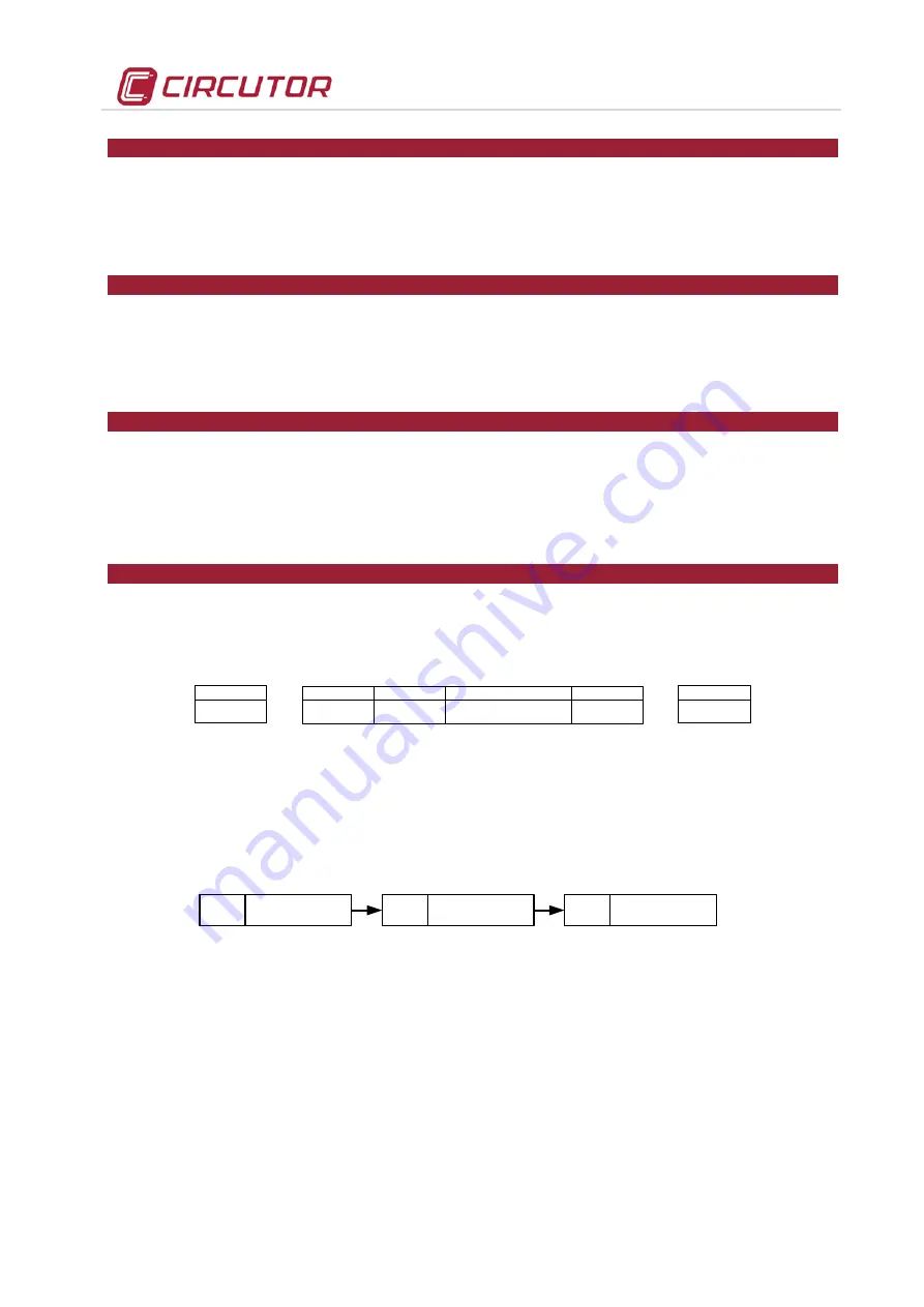
Fig. 12-1. Modbus RTU frame
The format for serial transmission of 1 byte is as follows: 1 start bit ; 8 data bits (LSB first) ; 1 bit for even /
odd parity or no bit for no parity ; 1 stop bit if parity is used or 2 bits if no parity (total 11 bits)
The Modbus specification defines a silent-interval (Pause) of at least 3.5 chars between two frames to
transmit. Within a message two chars may be separated for not more than 1.5 chars. A typical data
transmission looks like:
Pause
Frame 1
Pause
Frame 2
Pause
Frame 3
...
≥
3,5 char
≥
3,5 char
≥
3,5 char
Fig. 12-2. Modbus RTU sequence of frames
The CRC is a 16-bit type and it is calculated, in compliance with the Modbus standard, with the
polynomial X
16
+X
15
+X
2
+1.
In the “airLINK” network, the airGATEWAY implements the following function codes:
01 - READ COIL STATUS
02 - READ INPUT STATUS
03 - READ HOLDING REGISTER
04 - READ INPUT REGISTER
05 - FORCE SINGLE COIL
06 - PRESET SINGLE REGISTER


