Este manual es una guía de instalación para los interfaces
de comunicación de RS485 a radio
¡IMPORTANTE!
La manipulación o instalación incorrecta
del equipo puede ocasionar daños, tanto
personales como materiales. En particular la
manipulación bajo tensión puede producir la
muerte o lesiones graves por electrocución
al personal que lo manipula. Una instalación
o mantenimiento defectuoso comporta ade-
más riesgo de incendio. Lea detenidamente
el manual antes de conectar el equipo. Siga
todas las instrucciones de instalación y man-
tenimiento. En particular, respete las normas
de instalación indicadas en el Código Eléctrico
Nacional.
Si se utiliza el equipo de forma no especifica
-
da por el fabricante, la protección del equipo
puede resultar comprometida.
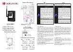
El equipo debe conectarse a un circuito de
alimentación protegido con fusibles tipo gl
(IEC 269) ó tipo M, comprendido entre 0.5 y
2A. Deberá estar previsto de un interruptor
magnetotérmico o dispositivo equivalente
para desconectar el equipo de la red de ali-
mentación.
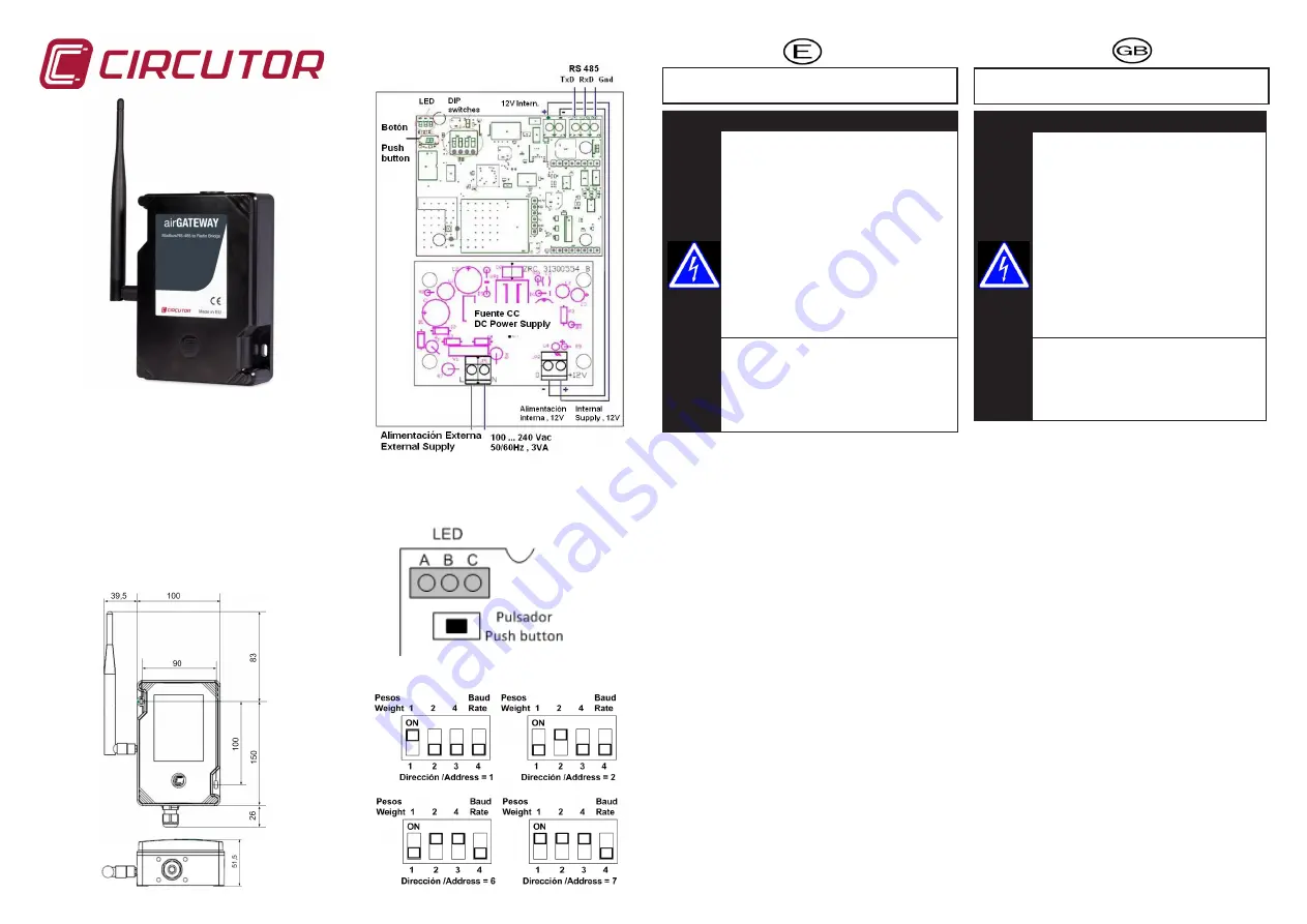
air GATEWAY
Interface RS485 a radio
RS 485 to radio interface
Interface RS485 à Radio
Schnittstelle RS 485 - Funk
Dimensiones /Dimensions
Esquema /Wire diagram
Direcciónamiento / Addressing
LED y Pulsador
LED and push button
1. DESCRIPCIÓN
El airGateway es un equipo que realiza la función de inter-
faz de comunicación entre un bus RS-485 con protocolo
ModBus y una red con enlace por radio. Este equipo actúa
como interfaz entre un supervisor externo y la red ZigBee
“airLINK”. Su función dentro de la red es la de coordinador,
participando activamente, por ejemplo, en la creación de la
red y en el mantenimiento del tráfico inalámbrico desde y
hacia otros dispositivos similares. Además, puede actuar
como equipo maestro de sensores alimentados por batería
de la misma familia.
El equipo necesita una alimentación CA o CC para poder
mantener la comunicación. Ver esquema y características
técnicas. Véase también el manual de configuración de la
red “airLink” (M98253901-01-xxx)
2. INSTALACIÓN
La instalación del equipo se realiza sobre panel. Ver croquis
de dimensiones. Para más detalles sobre la instalación y
puesta en marcha véase el manual M98250401-01-xxx ,
disponible en la web de CIRCUTOR SA, www.circutor. es ,
en el apartado de documentación / manuales
3. DIRECCIONAMIENTO
La dirección del equipo puede asignarse a través de los in-
terruptores DIP. Dichos interruptores sólo se leen al conectar
el circuito o después de un reset.
This is an installation guide for the communications interfa-
ces between RS485 to radio link.
¡IMPORTANT!
Incorrect handling or installation of this equi-
pment can cause personal injury or material
damage. In particular handling under power
may result in death or serious injury from elec-
trocution to personnel which manipulates the
device. Incorrect installation or maintenance
implies also a risk of fire. Carefully read the
manual before connecting the equipment.
Follow all instructions for installation and
maintenance of the device. In particular, ob-
serve the installation standards specified in
the National Electrical Code of your country.
If the instrument is not used as specified by
the manufacturer, the device protection can
be compromised.
The equipment must be connected to a power
supply circuit protected with gl type fuses
(IEC 269) or M type, with a size between 0.5
and 2A. The supply circuit must be provided
with a circuit breaker or equivalent device to
disconnect the equipment from the mains.
1. DESCRIPTION
The airGateway is an RS485 to radio interface using
Modbus protocol. Its purpose is to interface between an
external supervisor and an “airLINK” network (using ZigBee
compatible protocol). Its role in the network is as coordina-
tor, i.e. it forms an active part of creating the network and
maintaining wireless traffic from and to other similar devices.
Furthermore it can also work as parent or master device for
battery supplied sensors of the same family “airLINK”.
The device requires an AC or a DC power supply in order to
keep communication. (see schematic and technical features).
See also the manual on “airLINK” network Configuration
(M98253901-03-xxx)
2. INSTALLATION
Installation of the equipment is carried on panel. See
dimensional drawings. For details on the installation and
commissioning see M98250401-03-xxx manual, available on
the website of CIRCUTOR SA, www.circutor.es, in the section
on documentation / manuals
3. ADDRESSING
The device address can be assigned by means of the internal
DIP switches. Such switches are read only when connecting
the circuit to supply or after a reset.


