INSTALLATION
Page 19 of 36
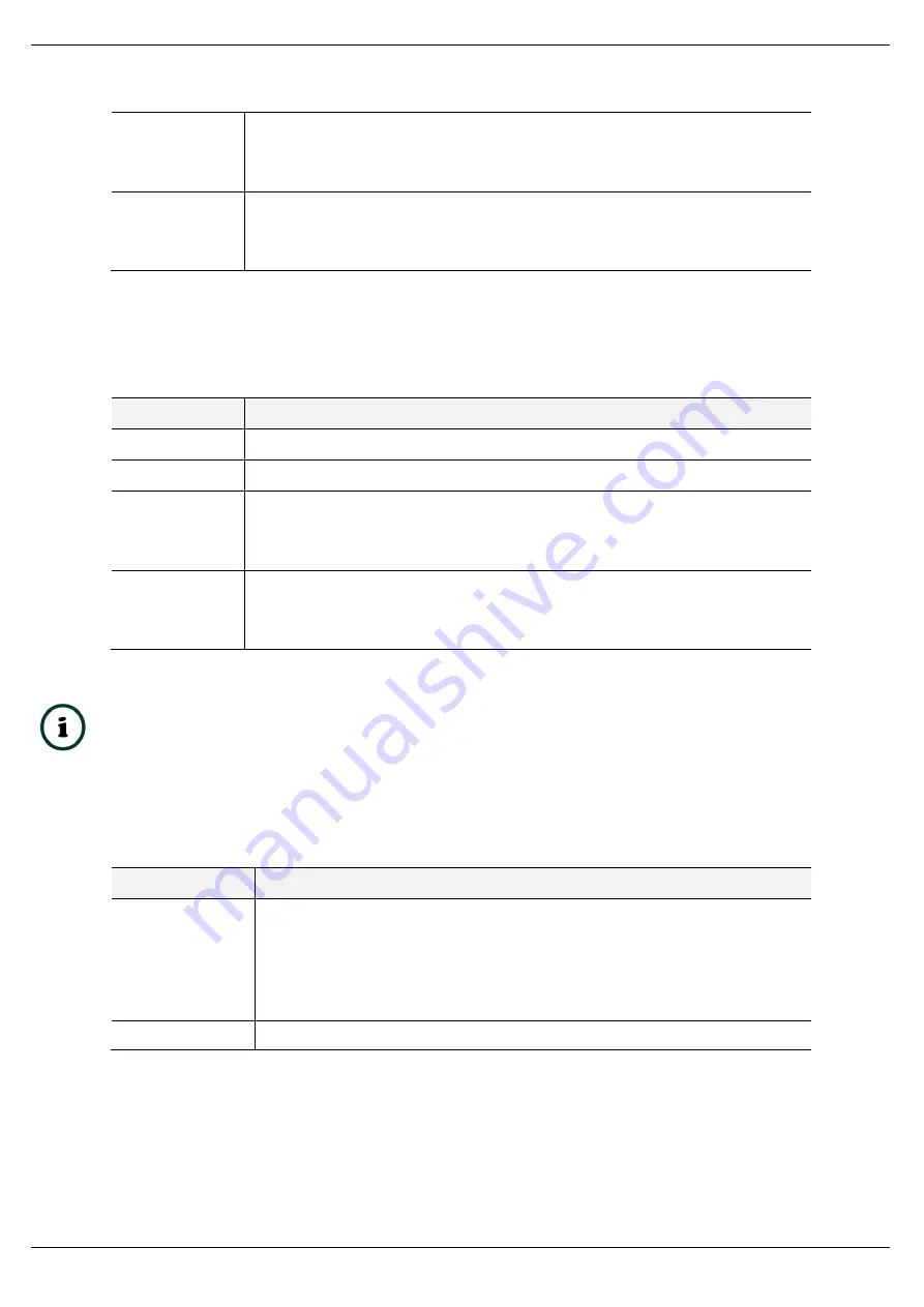
DIP Switch 3
This will force the module into a fixed IP address
– 192.168.1.100
0 = Normal
1 = Force Fixed IP
DIP Switch 4
This selects the PLC communications protocol.
0 = EtherNet/IP
1 = Modbus TCP
Table 2.3
–
System DIP Switch Settings
2.6.2. M
ODE
DIP
S
WITCHES
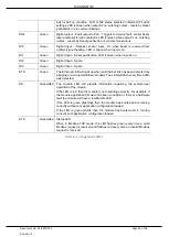
Mode DIP Switch Settings
DIP Switch
Description
DIP Switch 1
Reserved
– to be set to 1
DIP Switch 2
Reserved
DIP Switch 3
Trip Output (DO3) contact status
(*1)
0 = Contact closed for Healthy (no Trip)
1 = Contact open for Healthy (no Trip)
DIP Switch 4
Fault Output (DO4) contact status
(*2)
0 = Contact closed for Healthy (no Fault)
1 = Contact open for Healthy (no Fault)
Table 2.4
–
Mode DIP Switch Settings
Note 1:
“Trip” condition is triggered and latched for a detected belt rip condition. This
is used to Trip the conveyor belt.
Note 2:
“Fault” condition indicates a Reset Forced condition or a unit diagnostic fault
(Beam sensor fault or unit fault).
2.6.3. SW3
DIP
SWITCHES
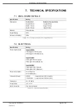
DIP Switch
Description
DIP Switch 1
Used to common the Digital input common (DI COM) to the internal 0V. When in the off
position, the DI COM is isolated from the internal 0V and the inputs are designed to
operate from an external power supply. In this mode, if no external power supply is used,
a bridge is required between DI COM and 0V.
0 = DI COM and 0V isolated
1 = DI Com and 0V common
DIP Switch 2
Not used for this device.
Table 2.5
–
SW3 DIP Switch Settings


