CV
-
100
-
P2100 Series | User Manual
68
3.13
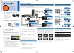
Connecting with CV Display Module
1.
Prepare the mounting kit that accompanied with P2100 as shown. (including two
mounting brackets and one screw pack)
2.
Remove the six screws at left and right panel.
3.
Assemble two mounting brackets by fastening six screws from the screws pack.
Summary of Contents for CV-100-P2100 Series
Page 18: ...CV 100 P2100 Series User Manual 18 Chapter 1 Product Introductions ...
Page 23: ...CV 100 P2100 Series User Manual 23 Dimensions CV 112 P2102 CV 112 P2102E ...
Page 25: ...CV 100 P2100 Series User Manual 25 Dimensions CV 115 P2102 CV 115 P2102E ...
Page 27: ...CV 100 P2100 Series User Manual 27 Dimensions CV W115 P2102 CV W115 P2102E ...
Page 29: ...CV 100 P2100 Series User Manual 29 Dimensions CV 117 P2102 CV 117 P2102E ...
Page 39: ...CV 100 P2100 Series User Manual 39 Chapter 2 Switches Connectors ...
Page 49: ...CV 100 P2100 Series User Manual 49 Chapter 3 System Setup ...
Page 73: ...CV 100 P2100 Series User Manual 73 ...
Page 75: ...CV 100 P2100 Series User Manual 75 Chapter 4 BIOS Setup ...
Page 94: ...CV 100 P2100 Series User Manual 94 Chapter 5 Product Application ...
Page 97: ...CV 100 P2100 Series User Manual 97 ...
Page 104: ...CV 100 P2100 Series User Manual 104 Reference Input Circuit Reference Output Circuit ...


