OPERATING MANUAL
TIG (GTAW) WELDING
6-4
Manual 0-5586
6.02 Setup for TIG (GTAW) Welding
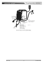
A. Connect the TIG Torch to the negative welding terminal (-). Welding current flows from the power source
via Dinse terminals. It is essential, however, that the male plug is inserted and turned securely to achieve
a sound electrical connection.
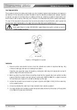
B. Connect the TIG torch trigger switch via the 8 pin socket located on the front of the power source as shown
below. The TIG torch will require a trigger switch to operate in Lift TIG Mode.
NOTE!
If the TIG torch has a remote TIG torch current control fitted then it will require to be connected to the 8 pin socket. (Refer
to Section 4.02.20 8 Pin Control Socket for further information).
C. Switch the Power Source On/Off switch located on the rear of the Power Source to the On position and
ensure the Power indicator on the Front Panel is illuminated.
D. Select Lift TIG mode with the process selection control (refer to Section 4.02.12 for further
information).
E. Connect the work lead to the positive welding terminal (+). Welding current flows from the Power Source
via Dinse terminals. It is essential, however, that the male plug is inserted and turned securely to achieve
a sound electrical connection.
F. Fit the welding grade shielding gas regulator/flowmeter to the shielding gas cylinder (refer to Section 6.01)
then connect the shielding gas hose from the TIG torch to the regulator/flowmeter outlet. Note that the TIG
torch shielding gas hose is connected directly to the regulator/flowmeter. Before turning on shielding gas
check that all fittings are tight and the gas valve on the TIG torch is turned off. The power source is not
fitted with a shielding gas solenoid to control the gas flow in TIG mode therefore the TIG torch will require
a gas valve (refer to Section 2.11 for optional TIG Torches). Before commencing to TIG weld open TIG
torch gas valve to allow sufficient shielding gas flow when welding. Refer to Section 6.03 for recommended
Shielding Gas flow rates and other TIG Welding information.
Note in TIG Mode an additional feature for Downslope is available. Refer to TIG Mode Advanced Features
Page 4-12.
Note when using a TIG Torch with Remote Current Control via the 8 Pin socket that in order to achieve full
TIG current range via the torch remote control the wirefeeder 10 pin control plug must be removed from
the 10 pin socket of the power source.
WARNING
Before connecting the work clamp to the work make sure the mains power supply is switched off.
!
WARNING
Secure the welding grade shielding gas cylinder in an upright position by chaining it to a
suitable stationary support to prevent falling or tipping.
!!
CAUTION
Loose welding terminal connections can cause overheating and result in the male plug being fused in the terminal.
Remove any packaging material prior to use. Do not block the air vents at the front or rear of the Welding Power Source.
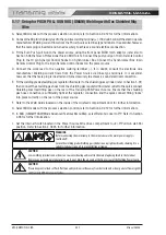
See over page for Setup for Lift TIG (GTAW) Welding diagram.
Summary of Contents for Transmig 355i
Page 8: ...This Page Intentionally Blank ...
Page 14: ...OPERATING MANUAL GENERAL INFORMATION 1 6 Manual 0 5586 This Page Intentionally Blank ...
Page 24: ...OPERATING MANUAL INTRODUCTION 2 10 Manual 0 5586 This Page Intentionally Blank ...
Page 28: ...OPERATING MANUAL INSTALLATION 3 4 Manual 0 5586 This Page Intentionally Blank ...
Page 84: ...OPERATING MANUAL TIG GTAW WELDING 6 10 Manual 0 5586 This Page Intentionally Blank ...
Page 110: ...OPERATING MANUAL KEY SPARE PARTS 9 4 Manual 0 5586 This page intentionally blank ...
Page 112: ...OPERATING MANUAL APPENDIX A 2 Manual 0 5550 This Page Intentionally Blank ...
Page 115: ...OPERATING MANUAL Transmig 220i This Page Intentionally Blank ...

