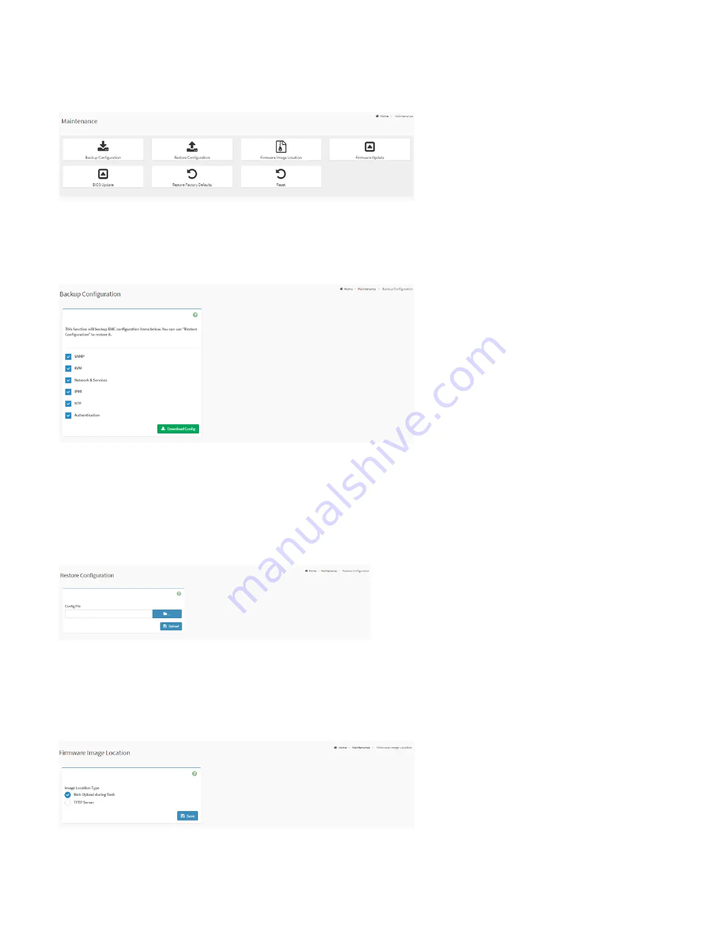
background image


115 


28.12 Maintenance  

This page is used to do maintenance tasks on the device. 


Maintenance Page 
 

28.12.1 Backup Configuration 


This page is used to back up the configuration. 


Backup Configuration Page 

 
Download Config: 

To download and save the configuration files backup from BMC to client system. 


28.12.2 Restore Configuration 

This page is used to restore the configuration files from the client system to the BMC. 


Restore Configuration Page 

Config File: 

This option is used to select the file which was backup earlier.


Upload: 

To upload the backup file to restore the backup files. 


28.12.3 Firmware Image Location  

This page is used to configure firmware image into the BMC. 


Firmware Image Location Page 


Web Upload during flash: 

Select the option to transfer the firmware image into the BMC via HTTP/HTTPS.


TFTP Server: 

Select the option to transfer the firmware image into the BMC via TFTP.


Summary of Contents for ORION HF210-G5

Page 1: ...ORION HF210 G5 User Manual...

Page 2: ...the server 1 Ensure that you follow the Safety Instruction 2 Ensure that your work surface is flat and clean to prevent the server cover from being scratched 3 Turn off your server 4 Disconnect all n...

Page 3: ...Pad 26 15 How to replace the CMOS battery 27 16 Replacing PCIE Card 29 16 1 Replacing PCIE Card 1 29 16 2 Replacing PCIE 2 Card 32 17 Removing and Installing Memory Modules 34 17 1 Removing Memory Mo...

Page 4: ...Settings 81 28 7 5 2 VMedia Instance Settings 81 28 7 5 3 Remote Session 82 28 7 6 Network Settings 83 28 7 6 1 Network IP Settings 83 28 7 6 2 Network Bond Configuration 85 28 7 6 3 DNS Configuratio...

Page 5: ...ocation 115 28 12 4 Firmware Update 116 28 12 5 BIOS Update 116 28 12 6 Restore Factory Defaults 117 28 12 7 Reset 117 28 13 Sign Out 118 29 Updating Bios and ME 119 30 Profile Loading in BIOS 126 31...

Page 6: ...ox ConnectX 3 4 5 and 6 Series ExaBlaze ExaNIC X10 X25 and X40 Series I O Ports 2 USB 3 1 Gen2 Type A 2 USB 3 1 Gen1 Type A 1 HDMI DB15 1 Serial Port DB9 2 10GbE RJ45 LAN 1 1GbE RJ45 LAN 1 1GbE RJ45 M...

Page 7: ...6 4 Chassis Overview The following illustrations are the ORION HF210 G5 chassis Front Back and Side views...

Page 8: ...7 5 Front Panel Components ITEM DESCRIPTION 1 2x USB 3 1 Gen1 2 Power Button 3 HDD LED 4 Power LED 5 Reset 6 2x Drive Bay...

Page 9: ...4 LAN RJ 45 Port IPMI_LAN 5 HDMI Port HDMI 6 10G LAN RJ 45 Port LAN1 7 10G LAN RJ 45 Port LAN2 8 USB 3 1 Gen2 Ports USB31_1_2 9 1G LAN RJ 45 Port LAN3 10 USB 3 1 Gen2 Ports USB31_3_4 11 1G LAN RJ 45 P...

Page 10: ...ludes 2 accessory boxes Accessory Box 1 with GPU Cables and Brackets Accessory Box 2 with 2 Power Cables Also the ORION HF210 G5 server includes 1 bezel box The rails bezel box and both accessory boxe...

Page 11: ...10 8 Labelling This section contains information on the different labels found on the server 8 1 Power supplies cage...

Page 12: ...11 8 2 Serial Number and Model Number Labels on Mylar Front Back 8 3 HDD trays Model Number Serial Number Model Number Serial Number...

Page 13: ...12 8 4 Support and Certification Labels...

Page 14: ...13 9 Chassis Layout The following illusration shows inside of the ORION HF210 G5 system...

Page 15: ...14 10 Motherboard Layout The following picture shows the motherboard layout in the ORION HF210 G5 system...

Page 16: ...Expansion Slot Slot 6 Gen3 x16 link auto switch to x8 link if Slot 4 is occupied Physical x16 EE x16 x8 from CPU shared with Slot 4 Slot 4 Gen3 x8 link Physical x8 EE x0 x8 from CPU shared with Slot 6...

Page 17: ...16 11 Detailed Motherboard Layout The following illustration shows the detailed motherboard layout in the ORION HF210 G5 system...

Page 18: ...Management Bus Header IPMB_1 16 Chassis Fan Connector FAN5 39 TPM Header TPM1 17 Chassis Fan Connector FAN6 40 Clear CMOS Pad CLRMOS1 18 Chassis Fan Connector FAN7 41 Thermal Sensor Header TR1 19 SATA...

Page 19: ...18 11 2 Jumper Functionality...

Page 20: ...19...

Page 21: ...reen STB PWR ready 2 FAN1_LED1 Amber FAN1 failed 3 FAN2_LED1 Amber FAN2 failed 4 FAN3_LED2 Amber FAN3 failed 5 FAN4_LED4 Amber FAN4 failed 6 FAN5_LED2 Amber FAN5 failed 7 FAN6_LED1 Amber FAN6 failed 8...

Page 22: ...21 11 4 Block Diagram...

Page 23: ...section contains information on how to remove the chassis cover from the system Step 1 Turn the Knob anti clockwise by using Philips screwdriver type 2 Step 2 Slide the Rear Top Cover towards the bac...

Page 24: ...over This section contains information on how to install the Chassis cover in the system Step 1 Slide the cover towards the front of the system to close the cover Step 2 Turn the Knob clockwise by usi...

Page 25: ...d 14 1 Clear CMOS by Battery Step 1 Power system off Step 2 Unplugged power cable from system Step 3 Take off the chassis top cover and then locate the CMOS battery on the motherboard Step 4 Press the...

Page 26: ...side and place the CMOS battery again gently Step 6 Cover up the Chassis top cover and then Plug the power cable back in Step 7 Turn system ON Step 8 Allow system to go through a complete power cycle...

Page 27: ...nder from the PCI e connector on the motherboard Step 4 Locate the clear CMOS Pad Squared in red Step 5 Use a flathead screwdriver or other piece of metal to short the two halves together for 30 secon...

Page 28: ...system Step 1 Power system off Step 2 Unplugged power cable from system Step 3 Take off the chassis top cover and then locate the CMOS battery on the motherboard Step 4 Press the lock on the left sid...

Page 29: ...side and replace the new CMOS battery gently Step 6 Cover up the Chassis top cover and then Plug the power cable back in Step 7 Turn system ON Step 8 Allow system to go through a complete power cycle...

Page 30: ...Ie Card This section contains information on how to replace the PCIe card 1 and 2 16 1 Replacing PCIE Card 1 Step 1 Pull the tab of the PCIe release latch and rotate to the top Step 2 Pull the PCIe ca...

Page 31: ...30 Step 3 Twist the card and remove from chassis...

Page 32: ...31 Step 4 Put another PCIe card in and install into the slot Step 5 Rotate and close the PCIe release latch...

Page 33: ...lacing PCIe 2 Card This section contains information on how to replace the PCIe 2 card Step 1 Pull the tab of the PCIe release latch and rotate to the top Step 2 Pull the PCIe card out of the slot and...

Page 34: ...33 Step 3 Put another PCIe card in and install into the slot Step 4 Rotate and close the PCIe release latch...

Page 35: ...Size Per DIMM Non ECC UDIMM 32GB 16GB 8GB 4GB Caution Handle each memory module only by the meomry cards edges ensuring not touching the middle of memory module or mettalic contacts 17 1 Removing Mem...

Page 36: ...ule Step 1 Identify the memory module socket Step 2 Make sure that the Memory Module Ejectors on both ends are released Step 3 Vertically press the memory module with your thumbs until the memory sits...

Page 37: ...36...

Page 38: ...eplacing Swappable SSD This section contains information on how to replace the swappable SSD in the front of the system Step 1 Flip the button to the right and the latch pops out Step 2 Pull out the S...

Page 39: ...38 Step 3 Turn over the cage and unscrew 4 screws Step 4 Replace the SSD...

Page 40: ...nsion slot Caution For all the GPUs used in the Orion HF210 G5 system please install the GPU bracket assembly before installing the card The GPU bracket assembly is provided in the accessory box Step...

Page 41: ...40 Step 3 Press down the PCIe slot lever and then pull the GPU out of slot Step 4 Twist the GPU and remove the GPU...

Page 42: ...41 Step 5 Remove the GPU bracket assembly and install to the new GPU Step 6 Align the metal plate on the GPU with the rear panel then drop down the GPU...

Page 43: ...42 Step 7 Slide the new GPU into the PCIe slot on the riser card Step 8 Fasten the screws to mount the GPU bracket assembly with the chassis base...

Page 44: ...43 Step 9 Rotate and close the PCIe release latch...

Page 45: ...44 20 Rack Mounting This section contains information on how to mount a system into the rack with the rack rails Step 1 Install the rails into the rack...

Page 46: ...p 2 Pull the inner and middle rails fully extended in lock position Pull the white release button to slide out the inner rail Step 3 Align the inner rail with the chassis mounting key push and slide t...

Page 47: ...46 Step 4 Horizontally slide the chassis into the middle rail until click Step 5 Pull Push the blue release button on the inner rail to unlock the chassis and then push the chassis into rack...

Page 48: ...47 21 Plugging the Power Cords The following illustration shows how to connect the power cords to the back of the system...

Page 49: ...48 22 Turning on the System The following illustration indicates where the power button is located on the front of the server...

Page 50: ...x70 DXE_SB_INIT 0xE2 PEI_S3_VIDEO_REPOST 0x71 DXE_SB_SMM_INIT 0xE3 PEI_S3_OS_WAKE 0x72 DXE_SB_DEVICES_INIT 0x50 PEI_MEMORY_INVALID_TYPE 0x78 DXE_ACPI_INIT 0x53 PEI_MEMORY_NOT_DETECTED 0x79 DXE_CSM_INI...

Page 51: ...e DEL or F2 button on the keyboard immediately after you see the following windows during the POST Power On Self Test to enter in to the Bios If you miss the step and would like to enter to the BIOS u...

Page 52: ...es such as Supervisor Password and Enabling Disabling Secure Boot Boot To set up the default system device to locate and load the Operating System Server Mgmt To manage the server such as System Event...

Page 53: ...BMC Web GUI 25 1 Configuring the BMC IP Address Settings for Remote management in BIOS Utility This section contains information on how to configure BMC IP address settings for remote management The...

Page 54: ...the IP address manually Step 3 Under the Configuration address source select either the Static or DHCP to choose the static IP address source If you select DHCP then IP address assignment is done auto...

Page 55: ...54 Step 4 If the Static IP selected then enter the values for the Station IP address Current Subnet mask and Current Router IP address Press F10 to Save and Exit to reboot the machine...

Page 56: ...tic BMC IP address settings for remote management in the BMC Web GUI Step 1 In order to configure the Static IP address through BMC Web GUI Turn ON the system and note down the BMC IP as seen below St...

Page 57: ...56 Step 3 When main menu of BMC appears then click on the Settings Step 4 Select the Network Settings...

Page 58: ...57 Step 5 Select the Network IP Settings Step 6 Uncheck the Enable IPv4 DHCP then enter the IPv4 Address IPv4 Subnet and IPv4 Gateway and then click on Save...

Page 59: ...58 Step 7 Click on OK and close the browser tab or browser Launch the browser or new tab with the new BMC IP Address to verify if the changes has been successful...

Page 60: ...ovides an interface to access BMC IPMI Management Console which is used to configure monitor and administer the ORION HF210 G5 systems This Web based GUI is supported on the following web browsers Sup...

Page 61: ...ommendation is that once you log in you change the root password Username Enter your username in this field Password Enter your password in this field Remember Username Check this option to remember y...

Page 62: ...61 28 Viewing and Configuring the BMC IPMI Management Console After you successfully log into your Management Console the Remote Management Console GUI appears...

Page 63: ...quick buttons are located at the top right of the Web GUI Quick Button and User Information Sync Click the button to synchronize with latest chassis state Refresh Click the button to reload the curren...

Page 64: ...mation displays the following information BMC Firmware Version Displays the BMC firmware version of the device BIOS Firmware Version Displays the BIOS firmware version of the device ME Firmware Versio...

Page 65: ...r DHCP V6 Network Mode The v6 network mode of the device can be either static or DHCP IPv6 Address The IPv6 address of the device can be static or DHCP 28 3 4 Sensor Monitoring Here lists all the avai...

Page 66: ...In this Sensor Reading page live readings for all the available sensors with details like Sensor Name Status and Current Reading are shown 28 4 1 Sensor detail Select a particular Sensor from the Cri...

Page 67: ...FRU Device Name The device name of the selected FRU device Chassis Information Chassis Information Area Format Version Chassis Type Chassis Part Number Chassis Serial Number Chassis Extra Board Inform...

Page 68: ...67 FRU File ID Product Extra...

Page 69: ...s page displays the list of event logs occurred by the different sensors on this device Double click on a record to see the details of that entry You can use the sensor type or sensor name filter opti...

Page 70: ...events with Client UTC Offset timestamp UTC Offset Displays the current UTC Offset value based on which event Time Stamps will be updated Clear MCA Log To delete MCA log Download MCA Log To download...

Page 71: ...70 28 7 Settings This group of pages allows you to access various configuration settings Settings Page...

Page 72: ...tains the UTC offset along with the locations and Manual UTC offset for NTP server which can be used to display the exact local time Primary NTP Server To configure a primary NTP server to use when au...

Page 73: ...7 2 1 LDAP E directory Settings LDAP is an Internet protocol that BMC can use to authenticate users If you have an LDAP server configured on your network you can use it as an easy way to add manage a...

Page 74: ...r Bind DN The Bind DN is used during bind operation which authenticates the client to the server Password The password of LDA E Directory server Search Base The Search base tells the LDAP server which...

Page 75: ...rks and domains Active Directory allows you to configure the Active Directory Server Settings The displayed table shows any configured Role Groups and the available slots You can modify add or delete...

Page 76: ...rivilege Enter the level of privilege User Administrator Operator OEM None to assign to this role group KVM Access Check the box to enable KVM access for the group VMedia Access Check the box to enabl...

Page 77: ...Check the box to enable Radius authentication Server Address The IP address of Radius server Port The port number of Radius server Secret The authentication secret of Radius server KVM Access Check th...

Page 78: ...strator with Vendor Specific Attribute in Server side Operator Configure Operator with Vendor Specific Attribute in Server side User Configure User with Vendor Specific Attribute in Server side OEM Pr...

Page 79: ...etting Page Relative Positioning Linux Relative mode sends the calculated relative mouse position displacement to the server Absolute Positioning Windows The absolute position of the local mouse is se...

Page 80: ...s Page 28 7 4 1 Log Settings Policy This page is used to configure the log policy for the event log Linear Storage Policy Check the option to enable linear storage policy for the event log Circular St...

Page 81: ...80 28 7 5 Media Redirection Settings This page is used to configure the media into BMC for redirection Media Redirection Settings Page...

Page 82: ...word to authenticate on the server Same settings for Floppy Harddisk Images Enable Disable to select same media type data configurations for all the remote media types Mount Floppy Check the box to en...

Page 83: ...n using JViewer Java KVM On changing this configuration KVM and VMedia Sessions will be restarted If this support is enabled KVM session will not use its dedicated port whereas both Web and KVM sessio...

Page 84: ...to enable the selected channel LAN Interface Lists the available LAN interfaces MAC Address Displays the MAC Address of the device This is a read only field Enable IPv4 Check the box to enable the IP...

Page 85: ...x to be configured for the selected channel E g 0 IPv6 Address Specify a static IPv6 address to be configured to the device for the selected channel E g 2004 2010 Subnet Prefix length Specify the subn...

Page 86: ...urations Network Bond Page Enable Bonding Check this option to enable network bonding for network interface Bond Mode This field displays the Network bonding mode Note this field is not configurable 2...

Page 87: ...f private type Domain Setting Select whether the domain interface will be configured manually or automatically Domain Interface This field will be present if specify Domain Setting to Automatic the fi...

Page 88: ...2 If Authentication fails the reason for failure could be invalid user or invalid password 3 If Radius Authentication fails we can t differentiate whether it is invalid user or invalid password So it...

Page 89: ...em power off system reset as well as triggering the generation of an alert Platform Event Filter Page 28 7 8 1 Event Filters This page is used to configure Event filters You can modify or add new even...

Page 90: ...ceived over Choose 0 if the event message is received via the system interface primary IPMB or internally generated by the BMC IPMB Device LUN Choose the corresponding IPMB device LUN if event is gene...

Page 91: ...90 28 7 8 2 Alert Policies This page is used to configure the Alert Policy for the PEF configuration You can add delete or modify an entry in this page Alert Policies Page...

Page 92: ...from the list LAN Channel Choose a particular channel from the available channel list Destination Selector Choose a particular destination from the configured destination list Event Specific Alert Str...

Page 93: ...on Address BMC User Name Email subject and Email message needs to be filled For SNMP Trap only the SNMP Destination Address has to be filled BMC User Name If Destination type is Email Alert then choos...

Page 94: ...splays the current status of the service either active or inactive state Interfaces It shows the interface in which service is running Nonsecure Port Displays non secure port number of the service Sec...

Page 95: ...icular session of the service Edit the existing service Click Edit icon to modify the configuration of the service Service Configuration Page Service Name Displays service name of the selected slot re...

Page 96: ...ary Username Enter the username to access SMTP Accounts Primary Password Enter the password for the SMTP User Account Primary SMTP SSLTLS Enable Check the box to enable SMTP SSLTLS protocol Primary SM...

Page 97: ...1 View SSL Certificate This page is used to view the uploaded SSL certificate in readable format View SSL certificate Page Note This page provides a simple method to generate SSL certificate and it is...

Page 98: ...Email Address E mail Address of the organization Valid for Validity of the certificate Key Length The key length bit value of the certificate 28 7 11 3 Upload SSL Certificate This page is used to uplo...

Page 99: ...e is used to configure general firewall settings General Firewall Settings Page Existing Firewall Settings This page is used to displays existing firewall settings Existing Firewall Settings Page Add...

Page 100: ...o displays existing IP rules Existing IP Rules Page Add IP Rule This page is used to displays add IP rule settings Add IP Rule Page IP Single or Range Start This field is used to configure the IP addr...

Page 101: ...This page is used to displays add port rule settings Add Port Rule Page Port Single or Range Start This field is used to configure the port number or range of port numbers Port Range End This field is...

Page 102: ...ect a free section and click on the empty section Add User Page Username Enter the name of the user Password Size Either 16 Bytes or 20 Bytes password size can be chosen Password Enter the password of...

Page 103: ...this mail format is Alert from your Host name The mail content shows sensor information ex Sensor type and Description Fixed Subject Format This format displays the message according to user s settin...

Page 104: ...103 28 7 14 Video Recording This page is used to configure video recording settings Video Recording Page...

Page 105: ...er the recording by the non recoverable events for Temperature Voltage sensor Fan state changed Events Trigger the recording by all fan sensor events Watchdog Timer Events Trigger the recording when w...

Page 106: ...he Share Type NFS CIFS If the selected share type is CIFS enter the User Name Password and Domain Name in the respective fields Pre Event Video Recordings This page used to configure the Pre Event vid...

Page 107: ...s page is used to configure share NIC NCSI PHY link up setting Keep Share NIC Link Up Page Enable Check the box to enable Keep Share NIC Link Up share NIC PHY will keep link up and it could avoid shar...

Page 108: ...s used to configure the Open Loop Control Table Open Loop Control Table Temp Select to set the values from 0 to 120 degree Celsius Duty Select to set the values from 20 to 100 28 7 16 2 Close Loop Con...

Page 109: ...peed up fan duty cycle The Time Seconds Of Speed Up Fan Duty Cycle To select the condition for time of speed up fan duty cycle 28 7 16 3 Temperature Sensor and Corresponding Fan Table This page is use...

Page 110: ...ode This page is to set the FAN Mode settings Fan Mode Page Set Fan Duty For Manual Mode To set the Fan Duty values for Manual Fans Set Fan Control Mode To set Fan Control Mode to be Default either Ma...

Page 111: ...0 28 7 17 CPU Profile Selection This page is to set the CPU Profiles settings You can select the overclock profiles and you must reboot the machine for the settings to take effect CPU Profile Selectio...

Page 112: ...ote Control This page is used to launch the remote console redirection Remote Control Page Launch KVM Click the button to open remote control KVM page Launch Java KVM Click the button to open Java KVM...

Page 113: ...D DVD Floppy and Hard disk Media Instance Displays total media instance count Image Name Displays the default recovery image name on the server Status Displays the status of the media Session Index Di...

Page 114: ...power off the server Power On Select this option to power on the server Power Cycle Select this option to first power off and then reboot the system cold boot Hard Reset Select this option to reboot...

Page 115: ...of the chassis UID Control Page Turn On Select this option to turn on UID Temporary On Select this option to temporary turn on UID 15 sec blink Turn Off Select this option to turn off UID 28 11 2 Pos...

Page 116: ...to restore the configuration files from the client system to the BMC Restore Configuration Page Config File This option is used to select the file which was backup earlier Upload To upload the backup...

Page 117: ...s 28 12 4 Firmware Update This page is used to update BMC firmware Firmware Update Page Preserve all Configuration To preserve all configuration Preserve Network Settings To preserve network settings...

Page 118: ...ctory Defaults Page Restore Factory Defaults Click the button to restore configuration to factory default settings the following settings will be restored SDR SEL IPMI Network NTP SSH KVM Authenticati...

Page 119: ...28 13 Sign Out Click Sign Out to perform log out from the Web GUI A Warning message will be prompted you to proceed further click OK to log out else Cancel to retain the Web GUI Sign Out Button and Pr...

Page 120: ...Lan port Step 2 Turn ON the machine Step 3 Note down the BMC IP address detected as shown in the screenshot Step 4 Turn off the machine Step 5 Go to you computer and open a browser IE or Chrome and th...

Page 121: ...120 Step 7 Click on ADVANCED Step 8 Click on Proceed to unsafe Step 9 Enter a Username admin and Password admin...

Page 122: ...121 Step 10 Click on Maintenance and then click on BIOS Update Step 11 Select the Preserve BIOS configuration and then click on Choose File...

Page 123: ...122 Step 12 Navigate the folder containing a BIOS then Select the BIOS and click on Open Step 13 Click on Start BIOS update...

Page 124: ...123 Step 14 Click on OK Step 15 Wait until the Processing Window completes...

Page 125: ...124 Step 16 Click on Proceed Step 17 Click on OK to proceed the BIOS update...

Page 126: ...125 Step 18 Wait until the BIOS update completes and then click on OK...

Page 127: ...e BIOS Step 1 Turn ON the machine Step 2 Press DEL or F2 continuously while the system is booting in order to get in to the BIOS Once in the BIOS navigate in to the OC Tweaker menu and verify the User...

Page 128: ...127 Step 4 Enter Ok to restore the profile Step 5 Press F10 and enter Yes to save the settings and then reboot the system...

Page 129: ...777 command to modify the file permissions for the OCProfile utility Step 5 Execute the following OCProfile command to download the overclocking profile To download a single overclocking profile OCPr...

Page 130: ...e profiles being downloaded from the source overclocking profiles system either through a remote or local system with linux OS having OCProfile utility Step 6 Type ls l to verify that the downloaded o...

Page 131: ...download a single overclocking profile OCProfile H IP address U username P password p 1 s OCProfileTest1 bin To download the multiple profiles OCProfile H IP address U username P password p 1 2 s OCP...

Page 132: ...profiles being uploaded to target system either through a remote system or local system with linux OS having OCProfile utility Step 6 To load and activate a profile in BIOS refer to the instructions...

Page 133: ...e drivers downloading and running common monitoring tools under Linux windows on the Orion HF210 G5 systems 32 1 Drivers Downloading The drivers are available on the Ciara s website https ciaratech co...

Page 134: ...ndex php s DPchQUsCEV1DKte Note This needs to be unzipped in the Linux For Ubuntu 18 04 20 04 or later enter the command apt install i7z to install and then go to step 3 Caution For Ubuntu 18 04 make...

Page 135: ..._Mhz for an actual frequency 32 3 Verifying CPU Frequency for Windows This sections contains the information how to download and monitor CPU frequencies in the Windows through HWiNFO64 utility The Hwi...

Reviews: