


ADJUSTER REAR DRUM BRAKE (AUTOMATIC)
The rear drum brakes on this vehicle automatically
adjust, when required, during the normal operation
of the vehicle every time the brakes are applied. Use
the following procedure to test the operation of the
automatic adjuster.
Place the vehicle on a hoist with a helper in the
driver’s seat to apply the brakes. Remove the access
plug from the adjustment hole in each brake support
plate to provide visual access of the brake adjuster
star wheel.
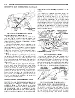
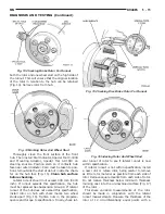
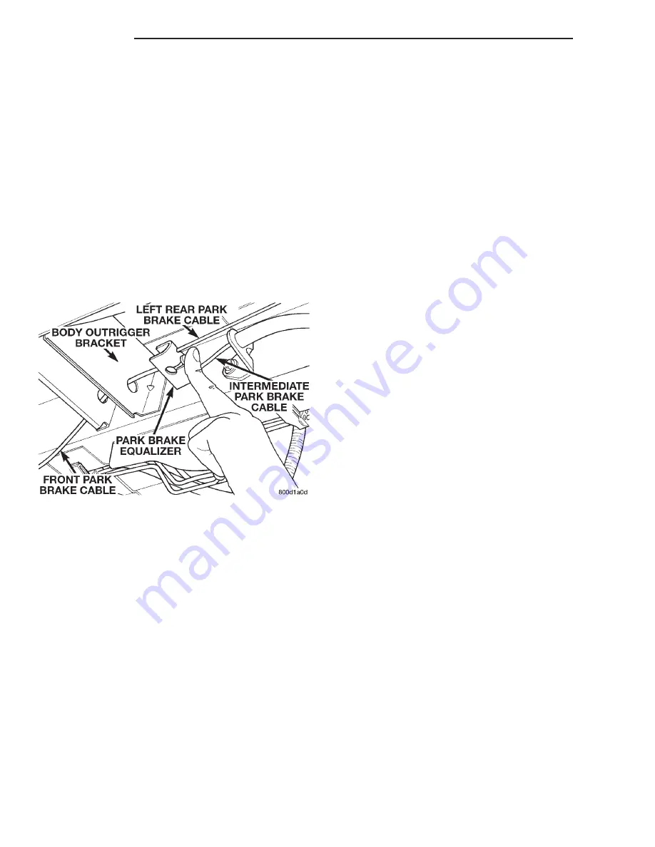
Remove the park brake cable, for the wheel of the
vehicle that is being worked on, from the park brake
cable equalizer (Fig. 12). This is required to gain
access to the star wheel. If the cable is not removed
from the equalizer, the cable and spring inside of the
brake drum is in the way of the star wheel.
To eliminate the condition where maximum adjust-
ment of the rear brake shoes, does not allow the
automatic adjuster to operate when tested, back the
star wheel off approximately 30 notches. It will be
necessary to hold the adjuster lever away from the
star wheel to permit this adjustment.
Have the helper apply the brakes. Upon applica-
tion of the brake pedal, the adjuster lever lever
should move down, turning the adjuster star wheel.
Thus, a definite rotation of the adjuster star wheel
can be observed if the automatic adjuster is working
properly. If one or more adjusters do not function
properly, the respective drum must be removed for
adjuster servicing.
BRAKE ROTOR
Any servicing of the rotor requires extreme care to
maintain the rotor to within service tolerances to
ensure proper brake action.
Before refinishing or refacing a rotor, the rotor
should be checked and inspected for the following
conditions:
Braking surface scoring, rust, impregnation of lin-
ing material and worn ridges.
Excessive rotor lateral runout or wobble.
Thickness variation in braking surface of the rotor
(Parallelism).
Dishing or distortion in braking surface of the
rotor (Flatness).
If a vehicle has not been driven for a period of
time, the rotors will rust in the area not covered by
the brake lining and cause noise and chatter when
the brakes are applied.
Excessive wear and scoring of the rotor can cause
temporary improper lining contact if ridges are not
removed from braking surface of rotor before instal-
lation of new brake shoe assemblies.
Some discoloration and/or wear of the rotor surface
is normal and does not require resurfacing when lin-
ings are replaced.
Excessive runout or wobble in a rotor can increase
pedal travel due to piston knock-back. This will also
increase guide pin bushing wear due to the tendency
of the caliper to follow rotor wobble.
Thickness variation in a rotor can also result in
pedal pulsation, chatter and surge due to variation in
brake output. This can also be caused by excessive
runout in the rotor and/or the hub.
Dishing or distortion can be caused by extreme
heat and abuse of the brakes.
CHECKING ROTOR FOR RUNOUT AND
THICKNESS
NOTE: The procedure for checking rotor runout
and thickness is the same for the front and rear
rotor. If there is a specification difference between
the front and rear rotor it will be designated as
such in the specifications of the following proce-
dure.
On-vehicle rotor runout is the combination of the
individual runout of the hub face and the runout of
the rotor. (The hub and rotor runouts are separable).
To measure runout on the vehicle, remove the wheel
and reinstall the lug nuts tightening the rotor to the
hub. Mount Dial Indicator, Special Tool C-3339 with
Mounting Adaptor, Special Tool SP- 1910 on steering
arm. Dial indicator plunger should contact braking
surface of rotor approximately 10 mm (0.393 in.)
from outer edge of rotor (Fig. 13). Check lateral
runout on both sides of rotor. Lateral runout of the
rotor should not exceed 0.13 mm (0.005 inch).
If lateral runout is in excess of the specification,
check the lateral runout of the hub face. Before
removing rotor from hub, make a chalk mark across
Fig. 12 Park Brake Cable Equlizer
5 - 14
BRAKES
NS
DIAGNOSIS AND TESTING (Continued)
Summary of Contents for 1998 Voyager
Page 8: ...FASTENER IDENTIFICATION NS INTRODUCTION 5 GENERAL INFORMATION Continued ...
Page 9: ...FASTENER STRENGTH 6 INTRODUCTION NS GENERAL INFORMATION Continued ...
Page 11: ...METRIC CONVERSION 8 INTRODUCTION NS GENERAL INFORMATION Continued ...
Page 12: ...TORQUE SPECIFICATIONS NS INTRODUCTION 9 GENERAL INFORMATION Continued ...
Page 16: ......
Page 26: ......
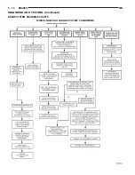
Page 93: ...RED BRAKE WARNING LAMP FUNCTION NS BRAKES 5 11 DIAGNOSIS AND TESTING Continued ...
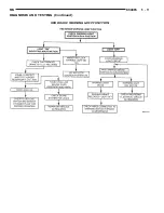
Page 94: ...POWER BRAKE SYSTEM DIAGNOSTICS 5 12 BRAKES NS DIAGNOSIS AND TESTING Continued ...
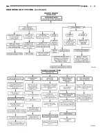
Page 95: ...VEHICLE ROAD TEST BRAKE NOISE NS BRAKES 5 13 DIAGNOSIS AND TESTING Continued ...
Page 222: ...COOLING SYSTEM DIAGNOSIS 7 8 COOLING SYSTEM NS DIAGNOSIS AND TESTING Continued ...
Page 223: ...NS COOLING SYSTEM 7 9 DIAGNOSIS AND TESTING Continued ...
Page 224: ...7 10 COOLING SYSTEM NS DIAGNOSIS AND TESTING Continued ...
Page 225: ...NS COOLING SYSTEM 7 11 DIAGNOSIS AND TESTING Continued ...
Page 226: ...7 12 COOLING SYSTEM NS DIAGNOSIS AND TESTING Continued ...
Page 280: ......
Page 286: ......
Page 289: ...CHARGING SYSTEM SCHEMATIC TYPICAL NS CHARGING SYSTEM 8C 3 DIAGNOSIS AND TESTING Continued ...
Page 291: ...CHARGING SYSTEM TEST NS CHARGING SYSTEM 8C 5 DIAGNOSIS AND TESTING Continued ...
Page 292: ...OVERCHARGE TEST 8C 6 CHARGING SYSTEM NS DIAGNOSIS AND TESTING Continued ...
Page 294: ...VOLTAGE DROP TEST 8C 8 CHARGING SYSTEM NS ...
Page 298: ......
Page 372: ......
Page 377: ...NS GS INSTRUMENT PANEL AND SYSTEMS 8E 5 DIAGNOSIS AND TESTING Continued ...
Page 378: ...8E 6 INSTRUMENT PANEL AND SYSTEMS NS GS DIAGNOSIS AND TESTING Continued ...
Page 379: ...NS GS INSTRUMENT PANEL AND SYSTEMS 8E 7 DIAGNOSIS AND TESTING Continued ...
Page 380: ...8E 8 INSTRUMENT PANEL AND SYSTEMS NS GS DIAGNOSIS AND TESTING Continued ...
Page 381: ...NS GS INSTRUMENT PANEL AND SYSTEMS 8E 9 DIAGNOSIS AND TESTING Continued ...
Page 382: ...8E 10 INSTRUMENT PANEL AND SYSTEMS NS GS DIAGNOSIS AND TESTING Continued ...
Page 383: ...NS GS INSTRUMENT PANEL AND SYSTEMS 8E 11 DIAGNOSIS AND TESTING Continued ...
Page 384: ...8E 12 INSTRUMENT PANEL AND SYSTEMS NS GS DIAGNOSIS AND TESTING Continued ...
Page 385: ...NS GS INSTRUMENT PANEL AND SYSTEMS 8E 13 DIAGNOSIS AND TESTING Continued ...
Page 386: ...8E 14 INSTRUMENT PANEL AND SYSTEMS NS GS DIAGNOSIS AND TESTING Continued ...
Page 402: ......
Page 428: ......
Page 440: ......
Page 478: ......
Page 496: ......
Page 504: ......
Page 508: ......
Page 524: ......
Page 542: ......
Page 546: ......
Page 550: ......
Page 559: ...SPECIAL TOOLS SPECIAL TOOL Degausser 6029 NS OVERHEAD CONSOLE 8V 9 ...
Page 560: ......
Page 562: ......
Page 564: ...8W 01 2 8W 01 GENERAL INFORMATION NS GS DESCRIPTION AND OPERATION Continued ...
Page 565: ...NS GS 8W 01 GENERAL INFORMATION 8W 01 3 DESCRIPTION AND OPERATION Continued ...
Page 580: ......
Page 616: ......
Page 660: ......
Page 664: ......
Page 704: ......
Page 718: ......
Page 728: ......
Page 740: ......
Page 744: ......
Page 758: ......
Page 768: ......
Page 784: ......
Page 792: ......
Page 796: ......
Page 800: ......
Page 814: ......
Page 822: ......
Page 826: ......
Page 832: ......
Page 836: ......
Page 840: ......
Page 876: ......
Page 1024: ......
Page 1220: ...Fig 3 Lubrication Lines 9 42 ENGINE NS GS DESCRIPTION AND OPERATION Continued ...
Page 1224: ...ENGINE DIAGNOSIS MECHANICAL CONT 9 46 ENGINE NS GS DIAGNOSIS AND TESTING Continued ...
Page 1286: ...Fig 5 Front Crossmember Dimensions 13 6 FRAME AND BUMPERS NS SPECIFICATIONS Continued ...
Page 1287: ...Fig 6 Engine Compartment Top View NS FRAME AND BUMPERS 13 7 SPECIFICATIONS Continued ...
Page 1289: ...Fig 8 Full Vehicle Bottom View NS FRAME AND BUMPERS 13 9 SPECIFICATIONS Continued ...
Page 1291: ...Fig 11 Body Side Openings NS FRAME AND BUMPERS 13 11 SPECIFICATIONS Continued ...
Page 1292: ......
Page 1302: ...FUEL PRESSURE BELOW SPECIFICATIONS 14 8 FUEL SYSTEM NS DIAGNOSIS AND TESTING Continued ...
Page 1304: ...FUEL INJECTOR DIAGNOSIS 14 10 FUEL SYSTEM NS DIAGNOSIS AND TESTING Continued ...
Page 1368: ......
Page 1426: ......
Page 1472: ......
Page 1479: ...Diagnosis Guide NS TRANSAXLE AND POWER TRANSFER UNIT 21 5 DIAGNOSIS AND TESTING Continued ...
Page 1480: ...Diagnosis Guide 21 6 TRANSAXLE AND POWER TRANSFER UNIT NS DIAGNOSIS AND TESTING Continued ...
Page 1481: ...Diagnosis Guide NS TRANSAXLE AND POWER TRANSFER UNIT 21 7 DIAGNOSIS AND TESTING Continued ...
Page 1482: ...Diagnosis Guide 21 8 TRANSAXLE AND POWER TRANSFER UNIT NS DIAGNOSIS AND TESTING Continued ...
Page 1483: ...Diagnosis Guide NS TRANSAXLE AND POWER TRANSFER UNIT 21 9 DIAGNOSIS AND TESTING Continued ...
Page 1484: ...Diagnosis Guide 21 10 TRANSAXLE AND POWER TRANSFER UNIT NS DIAGNOSIS AND TESTING Continued ...
Page 1485: ...Diagnosis Guide NS TRANSAXLE AND POWER TRANSFER UNIT 21 11 DIAGNOSIS AND TESTING Continued ...
Page 1486: ...Diagnosis Guide 21 12 TRANSAXLE AND POWER TRANSFER UNIT NS DIAGNOSIS AND TESTING Continued ...
Page 1656: ......
Page 1723: ...LEAD CORRECTION CHART NS TIRES AND WHEELS 22 5 DIAGNOSIS AND TESTING Continued ...
Page 1726: ...SPECIFICATIONS TIRE SPECIFICATIONS 22 8 TIRES AND WHEELS NS ...
Page 1866: ......
Page 1904: ......
Page 1928: ......