


either the crankshaft position sensor/camshaft posi-
tion sensor 8 volt supply circuit, or the camshaft
position sensor output or ground circuits. Use the
DRB scan tool to test the camshaft position sensor
and the sensor circuits. Refer to the appropriate Pow-
ertrain Diagnostics Procedure Manual. Refer to the
wiring diagrams section for circuit information.
IGNITION TIMING PROCEDURE
The engines for this vehicle, use a fixed ignition
system. The PCM regulates ignition timing. Basic
ignition timing is not adjustable.
MANIFOLD ABSOLUTE PRESSURE (MAP) SENSOR
TEST
Refer to Group 14, Fuel System for Diagnosis and
Testing.
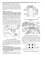
CAMSHAFT POSITION SENSOR AND CRANKSHAFT
POSITION SENSOR
The output voltage of a properly operating cam-
shaft position sensor or crankshaft position sensor
switches from high (5.0 volts) to low (0.3 volts). By
connecting an Moper Diagonostic System (MDS) and
engine analyzer to the vehicle, technicians can view
the square wave pattern.
ENGINE COOLANT TEMPERATURE SENSOR
Refer to Group 14, Fuel System for Diagnosis and
Testing.
INTAKE AIR TEMPERATURE SENSOR
Refer to Group 14, Fuel System, for Diagnosis and
Testing.
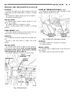
SPARK PLUG CONDITION
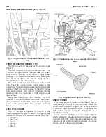
NORMAL OPERATING CONDITIONS
The few deposits present will be probably light tan
or slightly gray in color with most grades of commer-
cial gasoline (Fig. 23). There will not be evidence of
electrode burning. Gap growth will not average more
than approximately 0.025 mm (.001 in) per 1600 km
(1000 miles) of operation for non platinum spark
plugs. Non-platnium spark plugs that have normal
wear can usually be cleaned, have the electrodes filed
and regapped, and then reinstalled.
CAUTION: Never attempt to file the electrodes or
use a wire brush for cleaning platinum spark plugs.
This would damage the platinum pads which would
shorten spark plug life.
Some fuel refiners in several areas of the United
States have introduced a manganese additive (MMT)
for unleaded fuel. During combustion, fuel with MMT
may coat the entire tip of the spark plug with a rust
colored deposit. The rust color deposits can be misdi-
agnosed as being caused by coolant in the combustion
chamber. Spark plug performance is not affected by
MMT deposits.
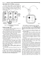
COLD FOULING (CARBON FOULING)
Cold fouling is sometimes referred to as carbon
fouling because the deposits that cause cold fouling
are basically carbon (Fig. 23). A dry, black deposit on
one or two plugs in a set may be caused by sticking
valves or misfire conditions. Cold (carbon) fouling of
the entire set may be caused by a clogged air cleaner.
Cold fouling is normal after short operating peri-
ods. The spark plugs do not reach a high enough
operating temperature during short operating peri-
ods. Replace carbon fouled plugs with new
spark plugs.
FUEL FOULING
A spark plug that is coated with excessive wet fuel
is called fuel fouled. This condition is normally
observed during hard start periods. Clean fuel
fouled spark plugs with compressed air and
reinstall them in the engine.
OIL FOULING
A spark plug that is coated with excessive wet oil
is oil fouled. In older engines, wet fouling can be
caused by worn rings or excessive cylinder wear.
Break-in fouling of new engines may occur before
normal oil control is achieved. Replace oil fouled
spark plugs with new ones.
OIL OR ASH ENCRUSTED
If one or more plugs are oil or ash encrusted, eval-
uate the engine for the cause of oil entering the com-
bustion chambers (Fig. 24). Sometimes fuel additives
can cause ash encrustation on an entire set of spark
Fig. 23 Normal Operation and Cold (Carbon) Fouling
NS
IGNITION SYSTEM
8D - 11
DIAGNOSIS AND TESTING (Continued)
Summary of Contents for 1998 Voyager
Page 8: ...FASTENER IDENTIFICATION NS INTRODUCTION 5 GENERAL INFORMATION Continued ...
Page 9: ...FASTENER STRENGTH 6 INTRODUCTION NS GENERAL INFORMATION Continued ...
Page 11: ...METRIC CONVERSION 8 INTRODUCTION NS GENERAL INFORMATION Continued ...
Page 12: ...TORQUE SPECIFICATIONS NS INTRODUCTION 9 GENERAL INFORMATION Continued ...
Page 16: ......
Page 26: ......
Page 93: ...RED BRAKE WARNING LAMP FUNCTION NS BRAKES 5 11 DIAGNOSIS AND TESTING Continued ...
Page 94: ...POWER BRAKE SYSTEM DIAGNOSTICS 5 12 BRAKES NS DIAGNOSIS AND TESTING Continued ...
Page 95: ...VEHICLE ROAD TEST BRAKE NOISE NS BRAKES 5 13 DIAGNOSIS AND TESTING Continued ...
Page 222: ...COOLING SYSTEM DIAGNOSIS 7 8 COOLING SYSTEM NS DIAGNOSIS AND TESTING Continued ...
Page 223: ...NS COOLING SYSTEM 7 9 DIAGNOSIS AND TESTING Continued ...
Page 224: ...7 10 COOLING SYSTEM NS DIAGNOSIS AND TESTING Continued ...
Page 225: ...NS COOLING SYSTEM 7 11 DIAGNOSIS AND TESTING Continued ...
Page 226: ...7 12 COOLING SYSTEM NS DIAGNOSIS AND TESTING Continued ...
Page 280: ......
Page 286: ......
Page 289: ...CHARGING SYSTEM SCHEMATIC TYPICAL NS CHARGING SYSTEM 8C 3 DIAGNOSIS AND TESTING Continued ...
Page 291: ...CHARGING SYSTEM TEST NS CHARGING SYSTEM 8C 5 DIAGNOSIS AND TESTING Continued ...
Page 292: ...OVERCHARGE TEST 8C 6 CHARGING SYSTEM NS DIAGNOSIS AND TESTING Continued ...
Page 294: ...VOLTAGE DROP TEST 8C 8 CHARGING SYSTEM NS ...
Page 298: ......
Page 372: ......
Page 377: ...NS GS INSTRUMENT PANEL AND SYSTEMS 8E 5 DIAGNOSIS AND TESTING Continued ...
Page 378: ...8E 6 INSTRUMENT PANEL AND SYSTEMS NS GS DIAGNOSIS AND TESTING Continued ...
Page 379: ...NS GS INSTRUMENT PANEL AND SYSTEMS 8E 7 DIAGNOSIS AND TESTING Continued ...
Page 380: ...8E 8 INSTRUMENT PANEL AND SYSTEMS NS GS DIAGNOSIS AND TESTING Continued ...
Page 381: ...NS GS INSTRUMENT PANEL AND SYSTEMS 8E 9 DIAGNOSIS AND TESTING Continued ...
Page 382: ...8E 10 INSTRUMENT PANEL AND SYSTEMS NS GS DIAGNOSIS AND TESTING Continued ...
Page 383: ...NS GS INSTRUMENT PANEL AND SYSTEMS 8E 11 DIAGNOSIS AND TESTING Continued ...
Page 384: ...8E 12 INSTRUMENT PANEL AND SYSTEMS NS GS DIAGNOSIS AND TESTING Continued ...
Page 385: ...NS GS INSTRUMENT PANEL AND SYSTEMS 8E 13 DIAGNOSIS AND TESTING Continued ...
Page 386: ...8E 14 INSTRUMENT PANEL AND SYSTEMS NS GS DIAGNOSIS AND TESTING Continued ...
Page 402: ......
Page 428: ......
Page 440: ......
Page 478: ......
Page 496: ......
Page 504: ......
Page 508: ......
Page 524: ......
Page 542: ......
Page 546: ......
Page 550: ......
Page 559: ...SPECIAL TOOLS SPECIAL TOOL Degausser 6029 NS OVERHEAD CONSOLE 8V 9 ...
Page 560: ......
Page 562: ......
Page 564: ...8W 01 2 8W 01 GENERAL INFORMATION NS GS DESCRIPTION AND OPERATION Continued ...
Page 565: ...NS GS 8W 01 GENERAL INFORMATION 8W 01 3 DESCRIPTION AND OPERATION Continued ...
Page 580: ......
Page 616: ......
Page 660: ......
Page 664: ......
Page 704: ......
Page 718: ......
Page 728: ......
Page 740: ......
Page 744: ......
Page 758: ......
Page 768: ......
Page 784: ......
Page 792: ......
Page 796: ......
Page 800: ......
Page 814: ......
Page 822: ......
Page 826: ......
Page 832: ......
Page 836: ......
Page 840: ......
Page 876: ......
Page 1024: ......
Page 1220: ...Fig 3 Lubrication Lines 9 42 ENGINE NS GS DESCRIPTION AND OPERATION Continued ...
Page 1224: ...ENGINE DIAGNOSIS MECHANICAL CONT 9 46 ENGINE NS GS DIAGNOSIS AND TESTING Continued ...
Page 1286: ...Fig 5 Front Crossmember Dimensions 13 6 FRAME AND BUMPERS NS SPECIFICATIONS Continued ...
Page 1287: ...Fig 6 Engine Compartment Top View NS FRAME AND BUMPERS 13 7 SPECIFICATIONS Continued ...
Page 1289: ...Fig 8 Full Vehicle Bottom View NS FRAME AND BUMPERS 13 9 SPECIFICATIONS Continued ...
Page 1291: ...Fig 11 Body Side Openings NS FRAME AND BUMPERS 13 11 SPECIFICATIONS Continued ...
Page 1292: ......
Page 1302: ...FUEL PRESSURE BELOW SPECIFICATIONS 14 8 FUEL SYSTEM NS DIAGNOSIS AND TESTING Continued ...
Page 1304: ...FUEL INJECTOR DIAGNOSIS 14 10 FUEL SYSTEM NS DIAGNOSIS AND TESTING Continued ...
Page 1368: ......
Page 1426: ......
Page 1472: ......
Page 1479: ...Diagnosis Guide NS TRANSAXLE AND POWER TRANSFER UNIT 21 5 DIAGNOSIS AND TESTING Continued ...
Page 1480: ...Diagnosis Guide 21 6 TRANSAXLE AND POWER TRANSFER UNIT NS DIAGNOSIS AND TESTING Continued ...
Page 1481: ...Diagnosis Guide NS TRANSAXLE AND POWER TRANSFER UNIT 21 7 DIAGNOSIS AND TESTING Continued ...
Page 1482: ...Diagnosis Guide 21 8 TRANSAXLE AND POWER TRANSFER UNIT NS DIAGNOSIS AND TESTING Continued ...
Page 1483: ...Diagnosis Guide NS TRANSAXLE AND POWER TRANSFER UNIT 21 9 DIAGNOSIS AND TESTING Continued ...
Page 1484: ...Diagnosis Guide 21 10 TRANSAXLE AND POWER TRANSFER UNIT NS DIAGNOSIS AND TESTING Continued ...
Page 1485: ...Diagnosis Guide NS TRANSAXLE AND POWER TRANSFER UNIT 21 11 DIAGNOSIS AND TESTING Continued ...
Page 1486: ...Diagnosis Guide 21 12 TRANSAXLE AND POWER TRANSFER UNIT NS DIAGNOSIS AND TESTING Continued ...
Page 1656: ......
Page 1723: ...LEAD CORRECTION CHART NS TIRES AND WHEELS 22 5 DIAGNOSIS AND TESTING Continued ...
Page 1726: ...SPECIFICATIONS TIRE SPECIFICATIONS 22 8 TIRES AND WHEELS NS ...
Page 1866: ......
Page 1904: ......
Page 1928: ......