


at running operating temperature the high pressure
inlet tank runs full and the low pressure outlet tank
drops:
•
Transmission oil will become hotter.
•
High reading shown on the temperature gauge.
•
Air in the coolant can cause loss of flow through
the heater.
•
Exhaust gas leaks into the coolant also can
cause the same problems.
DEAERATION
Air can only be removed from the system by gath-
ering under the pressure cap. On the next heat up it
will be pushed past the pressure cap into the CRS
tank by thermal expansion of the coolant. It then
escapes to the atmosphere in the CRS tank and is
replaced with solid coolant on cool down.
TEMPERATURE GAUGE INDICATION
At idle with Air Conditioning off the temperature
gauge will rise slowly to about 5/8 gauge travel, the
fan will come on and the gauge will quickly drop to
about 1/2 gauge travel. This is normal.
SERVICE PROCEDURES
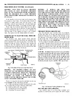
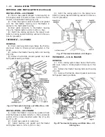
COOLANT LEVEL CHECK—ROUTINE
Do not remove radiator cap for routine cool-
ant level inspections.
The coolant reserve system provides a quick visual
method for determining the coolant level without
removing the radiator cap. With the engine cold
and not running, simply observe the level of the
coolant in the reserve tank (Fig. 3). The coolant level
should be between the minimum and maximum
marks.
COOLANT—ADDING ADDITIONAL
The radiator cap should not be removed.
When additional coolant is needed to maintain this
level, it should be added to the coolant reserve tank.
Use only 50/50 mix of ethylene glycol type antifreeze
and water.
CAUTION: Do not use well water, or suspect water
supply in cooling system. A 50/50 ethylene glycol
and distilled water mix is recommended.
COOLANT LEVEL SERVICE
The cooling system is closed and designed to main-
tain coolant level to the top of the radiator.
When servicing requires a coolant level check in
the radiator, the engine must be off and not under
pressure. Drain several ounces of coolant from the
radiator
draincock
while
observing
the
Coolant
Recovery System (CRS) Tank. Coolant level in the
CRS tank should drop slightly. Then remove the radi-
ator cap. The radiator should be full to the top. If
not, and the coolant level in the CRS tank is at the
MIN mark there is an air leak in the CRS system.
Check hose or hose connections to the CRS tank,
radiator filler neck or the pressure cap seal to the
radiator filler neck for leaks.
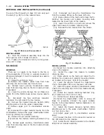
COOLING SYSTEM—DRAINING
Without removing radiator pressure cap and
with system not under pressure, shut engine off
and open draincock. The coolant reserve tank should
empty first, then remove radiator pressure cap. (if
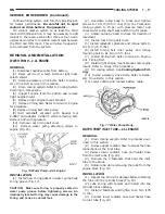
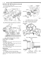
not, see Testing Cooling System for leaks). To vent
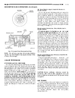
2.4L engine remove the coolant temperature sensor
located above water outlet housing (Fig. 15). The 3.0/
3.3/3.8L engines have an air bleed vent on the ther-
mostat.
Removal of a sensor is required because the ther-
mostat does not have an air vent. Sensor removal
allows an air bleed for coolant to drain from the
engine block.
COOLING SYSTEM—REFILLING
First clean system to remove old coolant, see Cool-
ing System Cleaning.
Fill the system, using the correct antifreeze as
described in the Coolant Section. Fill the system to
50 percent of its capacity with 100 percent glycol.
Then complete filling system with water. The 2.4L
engine requires venting by removal of the coolant
sensor on top of the water outlet connector (Fig. 15).
When coolant reaches this hole:
•
Install coolant sensor and tighten to 7 N·m (60
in. lbs.) for 2.4L Engines.
Fig. 15 Coolant Temperature Sensor—2.4L Engine
Drain/Fill
7 - 16
COOLING SYSTEM
NS
DIAGNOSIS AND TESTING (Continued)
Summary of Contents for 1998 Voyager
Page 8: ...FASTENER IDENTIFICATION NS INTRODUCTION 5 GENERAL INFORMATION Continued ...
Page 9: ...FASTENER STRENGTH 6 INTRODUCTION NS GENERAL INFORMATION Continued ...
Page 11: ...METRIC CONVERSION 8 INTRODUCTION NS GENERAL INFORMATION Continued ...
Page 12: ...TORQUE SPECIFICATIONS NS INTRODUCTION 9 GENERAL INFORMATION Continued ...
Page 16: ......
Page 26: ......
Page 93: ...RED BRAKE WARNING LAMP FUNCTION NS BRAKES 5 11 DIAGNOSIS AND TESTING Continued ...
Page 94: ...POWER BRAKE SYSTEM DIAGNOSTICS 5 12 BRAKES NS DIAGNOSIS AND TESTING Continued ...
Page 95: ...VEHICLE ROAD TEST BRAKE NOISE NS BRAKES 5 13 DIAGNOSIS AND TESTING Continued ...
Page 222: ...COOLING SYSTEM DIAGNOSIS 7 8 COOLING SYSTEM NS DIAGNOSIS AND TESTING Continued ...
Page 223: ...NS COOLING SYSTEM 7 9 DIAGNOSIS AND TESTING Continued ...
Page 224: ...7 10 COOLING SYSTEM NS DIAGNOSIS AND TESTING Continued ...
Page 225: ...NS COOLING SYSTEM 7 11 DIAGNOSIS AND TESTING Continued ...
Page 226: ...7 12 COOLING SYSTEM NS DIAGNOSIS AND TESTING Continued ...
Page 280: ......
Page 286: ......
Page 289: ...CHARGING SYSTEM SCHEMATIC TYPICAL NS CHARGING SYSTEM 8C 3 DIAGNOSIS AND TESTING Continued ...
Page 291: ...CHARGING SYSTEM TEST NS CHARGING SYSTEM 8C 5 DIAGNOSIS AND TESTING Continued ...
Page 292: ...OVERCHARGE TEST 8C 6 CHARGING SYSTEM NS DIAGNOSIS AND TESTING Continued ...
Page 294: ...VOLTAGE DROP TEST 8C 8 CHARGING SYSTEM NS ...
Page 298: ......
Page 372: ......
Page 377: ...NS GS INSTRUMENT PANEL AND SYSTEMS 8E 5 DIAGNOSIS AND TESTING Continued ...
Page 378: ...8E 6 INSTRUMENT PANEL AND SYSTEMS NS GS DIAGNOSIS AND TESTING Continued ...
Page 379: ...NS GS INSTRUMENT PANEL AND SYSTEMS 8E 7 DIAGNOSIS AND TESTING Continued ...
Page 380: ...8E 8 INSTRUMENT PANEL AND SYSTEMS NS GS DIAGNOSIS AND TESTING Continued ...
Page 381: ...NS GS INSTRUMENT PANEL AND SYSTEMS 8E 9 DIAGNOSIS AND TESTING Continued ...
Page 382: ...8E 10 INSTRUMENT PANEL AND SYSTEMS NS GS DIAGNOSIS AND TESTING Continued ...
Page 383: ...NS GS INSTRUMENT PANEL AND SYSTEMS 8E 11 DIAGNOSIS AND TESTING Continued ...
Page 384: ...8E 12 INSTRUMENT PANEL AND SYSTEMS NS GS DIAGNOSIS AND TESTING Continued ...
Page 385: ...NS GS INSTRUMENT PANEL AND SYSTEMS 8E 13 DIAGNOSIS AND TESTING Continued ...
Page 386: ...8E 14 INSTRUMENT PANEL AND SYSTEMS NS GS DIAGNOSIS AND TESTING Continued ...
Page 402: ......
Page 428: ......
Page 440: ......
Page 478: ......
Page 496: ......
Page 504: ......
Page 508: ......
Page 524: ......
Page 542: ......
Page 546: ......
Page 550: ......
Page 559: ...SPECIAL TOOLS SPECIAL TOOL Degausser 6029 NS OVERHEAD CONSOLE 8V 9 ...
Page 560: ......
Page 562: ......
Page 564: ...8W 01 2 8W 01 GENERAL INFORMATION NS GS DESCRIPTION AND OPERATION Continued ...
Page 565: ...NS GS 8W 01 GENERAL INFORMATION 8W 01 3 DESCRIPTION AND OPERATION Continued ...
Page 580: ......
Page 616: ......
Page 660: ......
Page 664: ......
Page 704: ......
Page 718: ......
Page 728: ......
Page 740: ......
Page 744: ......
Page 758: ......
Page 768: ......
Page 784: ......
Page 792: ......
Page 796: ......
Page 800: ......
Page 814: ......
Page 822: ......
Page 826: ......
Page 832: ......
Page 836: ......
Page 840: ......
Page 876: ......
Page 1024: ......
Page 1220: ...Fig 3 Lubrication Lines 9 42 ENGINE NS GS DESCRIPTION AND OPERATION Continued ...
Page 1224: ...ENGINE DIAGNOSIS MECHANICAL CONT 9 46 ENGINE NS GS DIAGNOSIS AND TESTING Continued ...
Page 1286: ...Fig 5 Front Crossmember Dimensions 13 6 FRAME AND BUMPERS NS SPECIFICATIONS Continued ...
Page 1287: ...Fig 6 Engine Compartment Top View NS FRAME AND BUMPERS 13 7 SPECIFICATIONS Continued ...
Page 1289: ...Fig 8 Full Vehicle Bottom View NS FRAME AND BUMPERS 13 9 SPECIFICATIONS Continued ...
Page 1291: ...Fig 11 Body Side Openings NS FRAME AND BUMPERS 13 11 SPECIFICATIONS Continued ...
Page 1292: ......
Page 1302: ...FUEL PRESSURE BELOW SPECIFICATIONS 14 8 FUEL SYSTEM NS DIAGNOSIS AND TESTING Continued ...
Page 1304: ...FUEL INJECTOR DIAGNOSIS 14 10 FUEL SYSTEM NS DIAGNOSIS AND TESTING Continued ...
Page 1368: ......
Page 1426: ......
Page 1472: ......
Page 1479: ...Diagnosis Guide NS TRANSAXLE AND POWER TRANSFER UNIT 21 5 DIAGNOSIS AND TESTING Continued ...
Page 1480: ...Diagnosis Guide 21 6 TRANSAXLE AND POWER TRANSFER UNIT NS DIAGNOSIS AND TESTING Continued ...
Page 1481: ...Diagnosis Guide NS TRANSAXLE AND POWER TRANSFER UNIT 21 7 DIAGNOSIS AND TESTING Continued ...
Page 1482: ...Diagnosis Guide 21 8 TRANSAXLE AND POWER TRANSFER UNIT NS DIAGNOSIS AND TESTING Continued ...
Page 1483: ...Diagnosis Guide NS TRANSAXLE AND POWER TRANSFER UNIT 21 9 DIAGNOSIS AND TESTING Continued ...
Page 1484: ...Diagnosis Guide 21 10 TRANSAXLE AND POWER TRANSFER UNIT NS DIAGNOSIS AND TESTING Continued ...
Page 1485: ...Diagnosis Guide NS TRANSAXLE AND POWER TRANSFER UNIT 21 11 DIAGNOSIS AND TESTING Continued ...
Page 1486: ...Diagnosis Guide 21 12 TRANSAXLE AND POWER TRANSFER UNIT NS DIAGNOSIS AND TESTING Continued ...
Page 1656: ......
Page 1723: ...LEAD CORRECTION CHART NS TIRES AND WHEELS 22 5 DIAGNOSIS AND TESTING Continued ...
Page 1726: ...SPECIFICATIONS TIRE SPECIFICATIONS 22 8 TIRES AND WHEELS NS ...
Page 1866: ......
Page 1904: ......
Page 1928: ......