


CAUTION:
The master cylinder is used to create
the seal for holding vacuum in the vacuum booster.
The vacuum seal on the master cylinder MUST be
replaced with a NEW seal whenever the master cyl-
inder is removed from the vacuum booster.
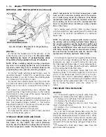
CAUTION: When removing the vacuum seal from
the master cylinder do not use a sharp tool.
(7) Using a soft tool such as a trim stick, remove
the vacuum seal from the master cylinder mounting
flange.
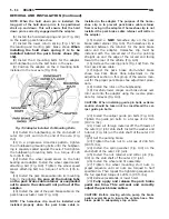
(8) Install a NEW vacuum seal on mounting flange
of the master cylinder (Fig. 128).
(9) Position master cylinder on studs of vacuum
booster, aligning push rod on vacuum booster with
master cylinder piston.
(10) Install the 2 nuts mounting the master cylin-
der to the vacuum booster (Fig. 124). Tighten both
mounting nuts to a torque of 25 N·m (225 in. lbs.).
(11) Install the wiper module drain hose (Fig. 124)
on the wiper module. Install the tie strap attaching
the wiper module drain hose to brake tube at the
master cylinder. Tie strap should be loosely tight-
ened so as not to collapse the wiper module
drain hose.
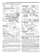
(12) Install the wiring harness connector on the
brake fluid level sensor in the master cylinder fluid
reservoir (Fig. 123).
(13) Install the throttle body and throttle cable
bracket on the intake manifold. Install the 2 bolts
(Fig. 122) attaching the throttle body to the intake
manifold and tighten to a torque of 25 N·m (225 in.
lbs.) Install clip (Fig. 122) attaching the wiring har-
ness to the throttle cable bracket.
(14) Install the wiring harness connectors on the
throttle position sensor and the AIS motor on throttle
body (Fig. 121).
(15) Install the wiring harness connector (Fig. 120)
on the EGR valve transducer.
(16) Install the battery tray. Install the 2 bolts and
the nut (Fig. 119) attaching the battery tray to the
vehicle. Tighten the 2 bolts and the nut to a torque of
14 N·m (125 in lbs.).
(17) If vehicle is equipped with speed control,
install the speed control servo and bracket on the
battery tray. Install and securely tighten bolt attach-
ing bracket to battery tray.
(18) If vehicle is equipped with speed control,
install the wiring harness connector on the speed
control servo. Then connect the vacuum lines onto
the speed control servo and vacuum reservoir on bat-
tery tray.
(19) Install the air inlet resonator and hoses as an
assembly on the throttle body and air cleaner hous-
ing (Fig. 118). Securely tighten hose clamp at air
cleaner housing and throttle body.
(20) Install the battery and the battery thermal
guard.
(21) Install the battery cables on the battery.
(22) Check the operation of the stop lamp switch
and adjust if necessary.
JUNCTION BLOCK
REMOVE
(1) Using a brake pedal depressor, move and lock
the brake pedal to a position past its first 1 inch of
travel. This will prevent brake fluid from draining
out of the master cylinder when the brake tubes are
removed from the junction block.
(2) Raise vehicle on jackstands or centered on a
hoist. See Hoisting in the Lubrication And Mainte-
nance Group of this service manual.
CAUTION: Before removing the brake tubes from
the junction block, the junction block and the brake
tubes must be thoroughly cleaned. This is required
to prevent contamination from entering the brake
hudraulic system.
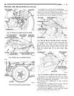
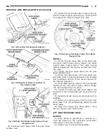
(3) Remove the 6 chassis brake tubes (Fig. 129)
from the junction block.
(4) Remove the bolt (Fig. 130) attaching the junc-
tion block mounting braket to the front suspension
cradle.
INSTALL
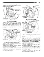
(1) Install the junction block and mounting bracket
(Fig. 130) on the front suspension cradle. Install the
attaching bolt and tighten to a torque of 28 N·m (250
in. lbs.).
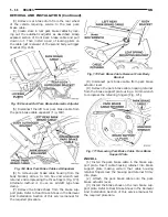
(2) Install the 6 chassis brake tubes (Fig. 131) into
the inlet and outlet ports of the junction block.
Fig. 128 Vacuum Seal Installed On Master Cylinder
NS
BRAKES
5 - 55
REMOVAL AND INSTALLATION (Continued)
Summary of Contents for 1998 Voyager
Page 8: ...FASTENER IDENTIFICATION NS INTRODUCTION 5 GENERAL INFORMATION Continued ...
Page 9: ...FASTENER STRENGTH 6 INTRODUCTION NS GENERAL INFORMATION Continued ...
Page 11: ...METRIC CONVERSION 8 INTRODUCTION NS GENERAL INFORMATION Continued ...
Page 12: ...TORQUE SPECIFICATIONS NS INTRODUCTION 9 GENERAL INFORMATION Continued ...
Page 16: ......
Page 26: ......
Page 93: ...RED BRAKE WARNING LAMP FUNCTION NS BRAKES 5 11 DIAGNOSIS AND TESTING Continued ...
Page 94: ...POWER BRAKE SYSTEM DIAGNOSTICS 5 12 BRAKES NS DIAGNOSIS AND TESTING Continued ...
Page 95: ...VEHICLE ROAD TEST BRAKE NOISE NS BRAKES 5 13 DIAGNOSIS AND TESTING Continued ...
Page 222: ...COOLING SYSTEM DIAGNOSIS 7 8 COOLING SYSTEM NS DIAGNOSIS AND TESTING Continued ...
Page 223: ...NS COOLING SYSTEM 7 9 DIAGNOSIS AND TESTING Continued ...
Page 224: ...7 10 COOLING SYSTEM NS DIAGNOSIS AND TESTING Continued ...
Page 225: ...NS COOLING SYSTEM 7 11 DIAGNOSIS AND TESTING Continued ...
Page 226: ...7 12 COOLING SYSTEM NS DIAGNOSIS AND TESTING Continued ...
Page 280: ......
Page 286: ......
Page 289: ...CHARGING SYSTEM SCHEMATIC TYPICAL NS CHARGING SYSTEM 8C 3 DIAGNOSIS AND TESTING Continued ...
Page 291: ...CHARGING SYSTEM TEST NS CHARGING SYSTEM 8C 5 DIAGNOSIS AND TESTING Continued ...
Page 292: ...OVERCHARGE TEST 8C 6 CHARGING SYSTEM NS DIAGNOSIS AND TESTING Continued ...
Page 294: ...VOLTAGE DROP TEST 8C 8 CHARGING SYSTEM NS ...
Page 298: ......
Page 372: ......
Page 377: ...NS GS INSTRUMENT PANEL AND SYSTEMS 8E 5 DIAGNOSIS AND TESTING Continued ...
Page 378: ...8E 6 INSTRUMENT PANEL AND SYSTEMS NS GS DIAGNOSIS AND TESTING Continued ...
Page 379: ...NS GS INSTRUMENT PANEL AND SYSTEMS 8E 7 DIAGNOSIS AND TESTING Continued ...
Page 380: ...8E 8 INSTRUMENT PANEL AND SYSTEMS NS GS DIAGNOSIS AND TESTING Continued ...
Page 381: ...NS GS INSTRUMENT PANEL AND SYSTEMS 8E 9 DIAGNOSIS AND TESTING Continued ...
Page 382: ...8E 10 INSTRUMENT PANEL AND SYSTEMS NS GS DIAGNOSIS AND TESTING Continued ...
Page 383: ...NS GS INSTRUMENT PANEL AND SYSTEMS 8E 11 DIAGNOSIS AND TESTING Continued ...
Page 384: ...8E 12 INSTRUMENT PANEL AND SYSTEMS NS GS DIAGNOSIS AND TESTING Continued ...
Page 385: ...NS GS INSTRUMENT PANEL AND SYSTEMS 8E 13 DIAGNOSIS AND TESTING Continued ...
Page 386: ...8E 14 INSTRUMENT PANEL AND SYSTEMS NS GS DIAGNOSIS AND TESTING Continued ...
Page 402: ......
Page 428: ......
Page 440: ......
Page 478: ......
Page 496: ......
Page 504: ......
Page 508: ......
Page 524: ......
Page 542: ......
Page 546: ......
Page 550: ......
Page 559: ...SPECIAL TOOLS SPECIAL TOOL Degausser 6029 NS OVERHEAD CONSOLE 8V 9 ...
Page 560: ......
Page 562: ......
Page 564: ...8W 01 2 8W 01 GENERAL INFORMATION NS GS DESCRIPTION AND OPERATION Continued ...
Page 565: ...NS GS 8W 01 GENERAL INFORMATION 8W 01 3 DESCRIPTION AND OPERATION Continued ...
Page 580: ......
Page 616: ......
Page 660: ......
Page 664: ......
Page 704: ......
Page 718: ......
Page 728: ......
Page 740: ......
Page 744: ......
Page 758: ......
Page 768: ......
Page 784: ......
Page 792: ......
Page 796: ......
Page 800: ......
Page 814: ......
Page 822: ......
Page 826: ......
Page 832: ......
Page 836: ......
Page 840: ......
Page 876: ......
Page 1024: ......
Page 1220: ...Fig 3 Lubrication Lines 9 42 ENGINE NS GS DESCRIPTION AND OPERATION Continued ...
Page 1224: ...ENGINE DIAGNOSIS MECHANICAL CONT 9 46 ENGINE NS GS DIAGNOSIS AND TESTING Continued ...
Page 1286: ...Fig 5 Front Crossmember Dimensions 13 6 FRAME AND BUMPERS NS SPECIFICATIONS Continued ...
Page 1287: ...Fig 6 Engine Compartment Top View NS FRAME AND BUMPERS 13 7 SPECIFICATIONS Continued ...
Page 1289: ...Fig 8 Full Vehicle Bottom View NS FRAME AND BUMPERS 13 9 SPECIFICATIONS Continued ...
Page 1291: ...Fig 11 Body Side Openings NS FRAME AND BUMPERS 13 11 SPECIFICATIONS Continued ...
Page 1292: ......
Page 1302: ...FUEL PRESSURE BELOW SPECIFICATIONS 14 8 FUEL SYSTEM NS DIAGNOSIS AND TESTING Continued ...
Page 1304: ...FUEL INJECTOR DIAGNOSIS 14 10 FUEL SYSTEM NS DIAGNOSIS AND TESTING Continued ...
Page 1368: ......
Page 1426: ......
Page 1472: ......
Page 1479: ...Diagnosis Guide NS TRANSAXLE AND POWER TRANSFER UNIT 21 5 DIAGNOSIS AND TESTING Continued ...
Page 1480: ...Diagnosis Guide 21 6 TRANSAXLE AND POWER TRANSFER UNIT NS DIAGNOSIS AND TESTING Continued ...
Page 1481: ...Diagnosis Guide NS TRANSAXLE AND POWER TRANSFER UNIT 21 7 DIAGNOSIS AND TESTING Continued ...
Page 1482: ...Diagnosis Guide 21 8 TRANSAXLE AND POWER TRANSFER UNIT NS DIAGNOSIS AND TESTING Continued ...
Page 1483: ...Diagnosis Guide NS TRANSAXLE AND POWER TRANSFER UNIT 21 9 DIAGNOSIS AND TESTING Continued ...
Page 1484: ...Diagnosis Guide 21 10 TRANSAXLE AND POWER TRANSFER UNIT NS DIAGNOSIS AND TESTING Continued ...
Page 1485: ...Diagnosis Guide NS TRANSAXLE AND POWER TRANSFER UNIT 21 11 DIAGNOSIS AND TESTING Continued ...
Page 1486: ...Diagnosis Guide 21 12 TRANSAXLE AND POWER TRANSFER UNIT NS DIAGNOSIS AND TESTING Continued ...
Page 1656: ......
Page 1723: ...LEAD CORRECTION CHART NS TIRES AND WHEELS 22 5 DIAGNOSIS AND TESTING Continued ...
Page 1726: ...SPECIFICATIONS TIRE SPECIFICATIONS 22 8 TIRES AND WHEELS NS ...
Page 1866: ......
Page 1904: ......
Page 1928: ......