


cause of low compression unless some malfunc-
tion is present.
(11)
Clean or replace spark plugs as necessary
and adjust gap as specified in Group 8, Electrical.
Tighten to specifications.
(12)
Test resistance of spark plug cables. Refer to
Group 8, Electrical Ignition System Secondary Cir-
cuit Inspection.
(13)
Test coil output voltage, primary and second-
ary resistance. Replace parts as necessary. Refer to
Group 8, Electrical Ignition System.
(14) Check fuel pump pressure at idle and differ-
ent RPM ranges. Refer to Group 14, Fuel System for
Specifications.
(15)
The air filter elements should be replaced as
specified in Group 0, Lubrication and Maintenance,.
(16)
Inspect crankcase ventilation system as out
lined in Group 0, Lubrication and Maintenance. For
emission controls see Group 25, Emission Controls
for service procedures.
(17) Inspect and adjust accessory belt drives refer-
ring to Group 7, Cooling System, Accessory Drive
Belts for proper adjustments.
(18)
Road test vehicle as a final test.
CYLINDER COMBUSTION PRESSURE LEAKAGE
TEST
The combustion pressure leakage test provides an
accurate means for determining engine condition.
Combustion pressure leakage testing will detect:
•
Exhaust and intake valve leaks (improper seat-
ing).
•
Leaks between adjacent cylinders or into water
jacket.
•
Any causes for combustion/compression pressure
loss.
WARNING:
DO NOT REMOVE THE RADIATOR CAP
WITH THE SYSTEM HOT AND UNDER PRESSURE
BECAUSE SERIOUS BURNS FROM COOLANT CAN
OCCUR.
Check the coolant level and fill as required. DO
NOT install the radiator cap.
Start and operate the engine until it attains nor-
mal operating temperature, then turn the engine
OFF.
Clean spark plug recesses with compressed air.
Remove the spark plugs.
Remove the oil filler cap.
Remove the air cleaner.
Calibrate the tester according to the manufactur-
er’s instructions. The shop air source for testing
should maintain 483 kPa (70 psi) minimum, 1 379
kPa (200 psi) maximum and 552 kPa (80 psi) recom-
mended.
Perform the test procedures on each cylinder
according to the tester manufacturer’s instructions.
While testing, listen for pressurized air escaping
through the throttle body, tailpipe and oil filler cap
opening. Check for bubbles in the radiator coolant.
All gauge pressure indications should be equal,
with no more than 25% leakage.
FOR EXAMPLE: At 552 kPa (80 psi) input pres-
sure, a minimum of 414 kPa (60 psi) should be main-
tained in the cylinder.
LASH ADJUSTER (TAPPET) NOISE DIAGNOSIS
A tappet-like noise may be produced from several
items. Check the following items.
(1) Engine oil level too high or too low. This may
cause aerated oil to enter the adjusters and cause
them to be spongy.
(2) Insufficient running time after rebuilding cylin-
der head. Low speed running up to 1 hour may be
required.
(3) During this time, turn engine off and let set for
a few minutes before restarting. Repeat this several
times after engine has reached normal operating
temperature.
(4) Low oil pressure.
(5) The oil restrictor pressed into the vertical oil
passage to the cylinder head is plugged with debris.
(6) Air ingested into oil due to broken or cracked
oil pump pick up.
(7) Worn valve guides.
(8) Rocker
arm
ears
contacting
valve
spring
retainer.
(9) Rocker arm loose, adjuster stuck or at maxi-
mum extension and still leaves lash in the system.
(10) Faulty lash adjuster.
a. Check
lash
adjusters
for
sponginess
while
installed in cylinder head. Depress part of rocker
arm over adjuster. Normal adjusters should feel very
firm. Spongy adjusters can be bottomed out easily.
b. Remove suspected lash adjusters, and disassem-
ble Do not reuse retainer caps. Do not inter-
change
parts
and
make
sure
that
care
and
cleanliness is exercised in the handling of parts.
c. Clean out dirt and varnish with solvent.
d. Reassemble with engine oil.
e. Check for sponginess.
f. If still spongy, replace with new adjuster.
INSPECTION (ENGINE OIL LEAKS IN GENERAL)
Begin with a through visual inspection of the
engine, particularly at the area of the suspected leak.
If an oil leak source is not readily identifiable, the
following steps should be followed:
(1) Do not clean or degrease the engine at this
time because some solvents may cause rubber to
swell, temporarily stopping the leak.
9 - 8
ENGINE
NS
DIAGNOSIS AND TESTING (Continued)
Summary of Contents for 1998 Voyager
Page 8: ...FASTENER IDENTIFICATION NS INTRODUCTION 5 GENERAL INFORMATION Continued ...
Page 9: ...FASTENER STRENGTH 6 INTRODUCTION NS GENERAL INFORMATION Continued ...
Page 11: ...METRIC CONVERSION 8 INTRODUCTION NS GENERAL INFORMATION Continued ...
Page 12: ...TORQUE SPECIFICATIONS NS INTRODUCTION 9 GENERAL INFORMATION Continued ...
Page 16: ......
Page 26: ......
Page 93: ...RED BRAKE WARNING LAMP FUNCTION NS BRAKES 5 11 DIAGNOSIS AND TESTING Continued ...
Page 94: ...POWER BRAKE SYSTEM DIAGNOSTICS 5 12 BRAKES NS DIAGNOSIS AND TESTING Continued ...
Page 95: ...VEHICLE ROAD TEST BRAKE NOISE NS BRAKES 5 13 DIAGNOSIS AND TESTING Continued ...
Page 222: ...COOLING SYSTEM DIAGNOSIS 7 8 COOLING SYSTEM NS DIAGNOSIS AND TESTING Continued ...
Page 223: ...NS COOLING SYSTEM 7 9 DIAGNOSIS AND TESTING Continued ...
Page 224: ...7 10 COOLING SYSTEM NS DIAGNOSIS AND TESTING Continued ...
Page 225: ...NS COOLING SYSTEM 7 11 DIAGNOSIS AND TESTING Continued ...
Page 226: ...7 12 COOLING SYSTEM NS DIAGNOSIS AND TESTING Continued ...
Page 280: ......
Page 286: ......
Page 289: ...CHARGING SYSTEM SCHEMATIC TYPICAL NS CHARGING SYSTEM 8C 3 DIAGNOSIS AND TESTING Continued ...
Page 291: ...CHARGING SYSTEM TEST NS CHARGING SYSTEM 8C 5 DIAGNOSIS AND TESTING Continued ...
Page 292: ...OVERCHARGE TEST 8C 6 CHARGING SYSTEM NS DIAGNOSIS AND TESTING Continued ...
Page 294: ...VOLTAGE DROP TEST 8C 8 CHARGING SYSTEM NS ...
Page 298: ......
Page 372: ......
Page 377: ...NS GS INSTRUMENT PANEL AND SYSTEMS 8E 5 DIAGNOSIS AND TESTING Continued ...
Page 378: ...8E 6 INSTRUMENT PANEL AND SYSTEMS NS GS DIAGNOSIS AND TESTING Continued ...
Page 379: ...NS GS INSTRUMENT PANEL AND SYSTEMS 8E 7 DIAGNOSIS AND TESTING Continued ...
Page 380: ...8E 8 INSTRUMENT PANEL AND SYSTEMS NS GS DIAGNOSIS AND TESTING Continued ...
Page 381: ...NS GS INSTRUMENT PANEL AND SYSTEMS 8E 9 DIAGNOSIS AND TESTING Continued ...
Page 382: ...8E 10 INSTRUMENT PANEL AND SYSTEMS NS GS DIAGNOSIS AND TESTING Continued ...
Page 383: ...NS GS INSTRUMENT PANEL AND SYSTEMS 8E 11 DIAGNOSIS AND TESTING Continued ...
Page 384: ...8E 12 INSTRUMENT PANEL AND SYSTEMS NS GS DIAGNOSIS AND TESTING Continued ...
Page 385: ...NS GS INSTRUMENT PANEL AND SYSTEMS 8E 13 DIAGNOSIS AND TESTING Continued ...
Page 386: ...8E 14 INSTRUMENT PANEL AND SYSTEMS NS GS DIAGNOSIS AND TESTING Continued ...
Page 402: ......
Page 428: ......
Page 440: ......
Page 478: ......
Page 496: ......
Page 504: ......
Page 508: ......
Page 524: ......
Page 542: ......
Page 546: ......
Page 550: ......
Page 559: ...SPECIAL TOOLS SPECIAL TOOL Degausser 6029 NS OVERHEAD CONSOLE 8V 9 ...
Page 560: ......
Page 562: ......
Page 564: ...8W 01 2 8W 01 GENERAL INFORMATION NS GS DESCRIPTION AND OPERATION Continued ...
Page 565: ...NS GS 8W 01 GENERAL INFORMATION 8W 01 3 DESCRIPTION AND OPERATION Continued ...
Page 580: ......
Page 616: ......
Page 660: ......
Page 664: ......
Page 704: ......
Page 718: ......
Page 728: ......
Page 740: ......
Page 744: ......
Page 758: ......
Page 768: ......
Page 784: ......
Page 792: ......
Page 796: ......
Page 800: ......
Page 814: ......
Page 822: ......
Page 826: ......
Page 832: ......
Page 836: ......
Page 840: ......
Page 876: ......
Page 1024: ......
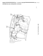
Page 1220: ...Fig 3 Lubrication Lines 9 42 ENGINE NS GS DESCRIPTION AND OPERATION Continued ...
Page 1224: ...ENGINE DIAGNOSIS MECHANICAL CONT 9 46 ENGINE NS GS DIAGNOSIS AND TESTING Continued ...
Page 1286: ...Fig 5 Front Crossmember Dimensions 13 6 FRAME AND BUMPERS NS SPECIFICATIONS Continued ...
Page 1287: ...Fig 6 Engine Compartment Top View NS FRAME AND BUMPERS 13 7 SPECIFICATIONS Continued ...
Page 1289: ...Fig 8 Full Vehicle Bottom View NS FRAME AND BUMPERS 13 9 SPECIFICATIONS Continued ...
Page 1291: ...Fig 11 Body Side Openings NS FRAME AND BUMPERS 13 11 SPECIFICATIONS Continued ...
Page 1292: ......
Page 1302: ...FUEL PRESSURE BELOW SPECIFICATIONS 14 8 FUEL SYSTEM NS DIAGNOSIS AND TESTING Continued ...
Page 1304: ...FUEL INJECTOR DIAGNOSIS 14 10 FUEL SYSTEM NS DIAGNOSIS AND TESTING Continued ...
Page 1368: ......
Page 1426: ......
Page 1472: ......
Page 1479: ...Diagnosis Guide NS TRANSAXLE AND POWER TRANSFER UNIT 21 5 DIAGNOSIS AND TESTING Continued ...
Page 1480: ...Diagnosis Guide 21 6 TRANSAXLE AND POWER TRANSFER UNIT NS DIAGNOSIS AND TESTING Continued ...
Page 1481: ...Diagnosis Guide NS TRANSAXLE AND POWER TRANSFER UNIT 21 7 DIAGNOSIS AND TESTING Continued ...
Page 1482: ...Diagnosis Guide 21 8 TRANSAXLE AND POWER TRANSFER UNIT NS DIAGNOSIS AND TESTING Continued ...
Page 1483: ...Diagnosis Guide NS TRANSAXLE AND POWER TRANSFER UNIT 21 9 DIAGNOSIS AND TESTING Continued ...
Page 1484: ...Diagnosis Guide 21 10 TRANSAXLE AND POWER TRANSFER UNIT NS DIAGNOSIS AND TESTING Continued ...
Page 1485: ...Diagnosis Guide NS TRANSAXLE AND POWER TRANSFER UNIT 21 11 DIAGNOSIS AND TESTING Continued ...
Page 1486: ...Diagnosis Guide 21 12 TRANSAXLE AND POWER TRANSFER UNIT NS DIAGNOSIS AND TESTING Continued ...
Page 1656: ......
Page 1723: ...LEAD CORRECTION CHART NS TIRES AND WHEELS 22 5 DIAGNOSIS AND TESTING Continued ...
Page 1726: ...SPECIFICATIONS TIRE SPECIFICATIONS 22 8 TIRES AND WHEELS NS ...
Page 1866: ......
Page 1904: ......
Page 1928: ......