


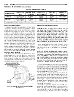


(5) With the aid of a helper, apply pressure to the
brake pedal until a pressure of 6895 kPa (1000 psi) is
obtained on the proportioning valve inlet gauge.
Then based on the type of brake system the vehicle is
equipped with and the pressure specification shown
on the following table, compare the pressure reading
on the outlet gauge to the specification. If outlet
pressure at the proportioning valve is not within
specification
when
required
inlet
pressure
is
obtained, replace the proportioning valve.
(6) Remove the pressure test fittings and pressure
gauges from the proportioning valve.
(7) Install the chassis brake lines in the correct
ports of the proportioning valve.
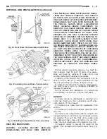
(8) Install the pressure test fittings and pressure
gauges in the opposite inlet and outlet port of the
height sensing proportioning valve. Repeat steps 4
and 5 for the other proportioning valve.
(9) Remove the pressure test fittings and pressure
gauges from the proportioning valve.
(10) Install the chassis brake lines in the correct
ports of the proportioning valve.
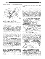
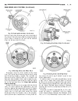
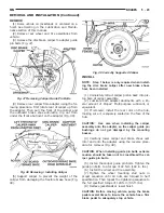
(11) Install the actuator (Fig. 22) on the height
sensing proportioning valve. Adjust the proportioning
valve actuator. See Height Sensing Proportioning
Valve in the Adjustment Section in this group of the
service manual for the adjustment procedure.
(12) Bleed both rear hydraulic circuits at the rear
brakes.
(13) Road test vehicle.
BRAKE FLUID CONTAMINATION
Indications of fluid contamination are swollen or deteri-
orated rubber parts.
Swollen rubber parts indicate the presence of
petroleum in the brake fluid.
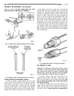
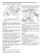
To test for contamination, put a small amount of
drained brake fluid in clear glass jar. If fluid sepa-
rates into layers, there is mineral oil or other fluid
contamination of the brake fluid.
If brake fluid is contaminated, drain and thor-
oughly flush system. Replace master cylinder, propor-
tioning valve, caliper seals, wheel cylinder seals,
Antilock Brakes hydraulic unit and all hydraulic
fluid hoses.
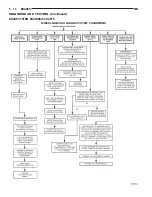
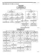
RED BRAKE WARNING LAMP TEST
For diagnosis of specific problems with the red
brake warning lamp system, refer to Brake System
Diagnostics Chart 2, located in the Diagnosis And
Testing section in this group of the service manual.
TRACTION CONTROL LAMP TEST
The traction control light is tested by cycling the
traction control switch on and off. The traction con-
trol switch used on this vehicle is a momentary con-
tact type switch. The test procedure for the traction
control light is performed as follows: Press the trac-
tion control switch once and the “Trac Off” lamp will
illuminate. With the “Trac Off” lamp illuminated,
press the traction control switch again and the “Trac
Off” lamp will turn off.
If the traction control lamp does not function as
described in the test above, diagnosis of the traction
control switch, lamp, wiring and other related compo-
nents of the traction control system is required.
STOP LAMP SWITCH TEST PROCEDURE
The required procedure for testing the stop lamp
switch is covered in Group 8H, Vehicle Speed Control
System in this service manual. The electrical circuit
tests for stop lamps is covered in Group 8W Rear-
Lighting in this service manual.
WHEEL
BASE
DRIVE
TRAIN
SALES CODE
BRAKE SYS-
TEM
SPLIT POINT
SLOPE
INLET PRES-
SURE PSI
OUTLET
PRESSURE
PSI
SWB
FWD
BRA+BGF
14
9
DISC/DRUM
W/O ANTILOCK
VAR.
.30
1000 PSI
250-350 PSI
SWB
FWD
BRA+BGF
BRB+BGF
BRV+BGF
14
9
,15
9
,15
9
HD
DISC/DRUM
WITH ANTILOCK
25 BAR
.59
1000 PSI
660-780
PSI
LWB
FWD
BRA+BGF
14
9
DISC/DRUM
W/O ANTILOCK
VAR.
.30
1000 PSI
250-350 PSI
LWB
FWD
BRA+BGF
BRB+BGF
BRV+BGF
14
9
,15
9
,15
9
HD
DISC/DRUM
WITH ANTILOCK
25 BAR
.59
1000 PSI
660-780 PSI
SWB
AWD
BRE+BGF
15
9
DISC/DISC
WITH ANTILOCK
25 BAR
.36
1000 PSI
525-640 PSI
LWB
AWD
BRE+BGF
15
9
DISC/DISC
WITH ANTILOCK
41 BAR
.36
1000 PSI
690-800 PSI
NS
BRAKES
5 - 19
DIAGNOSIS AND TESTING (Continued)
Summary of Contents for 1998 Voyager
Page 8: ...FASTENER IDENTIFICATION NS INTRODUCTION 5 GENERAL INFORMATION Continued ...
Page 9: ...FASTENER STRENGTH 6 INTRODUCTION NS GENERAL INFORMATION Continued ...
Page 11: ...METRIC CONVERSION 8 INTRODUCTION NS GENERAL INFORMATION Continued ...
Page 12: ...TORQUE SPECIFICATIONS NS INTRODUCTION 9 GENERAL INFORMATION Continued ...
Page 16: ......
Page 26: ......
Page 93: ...RED BRAKE WARNING LAMP FUNCTION NS BRAKES 5 11 DIAGNOSIS AND TESTING Continued ...
Page 94: ...POWER BRAKE SYSTEM DIAGNOSTICS 5 12 BRAKES NS DIAGNOSIS AND TESTING Continued ...
Page 95: ...VEHICLE ROAD TEST BRAKE NOISE NS BRAKES 5 13 DIAGNOSIS AND TESTING Continued ...
Page 222: ...COOLING SYSTEM DIAGNOSIS 7 8 COOLING SYSTEM NS DIAGNOSIS AND TESTING Continued ...
Page 223: ...NS COOLING SYSTEM 7 9 DIAGNOSIS AND TESTING Continued ...
Page 224: ...7 10 COOLING SYSTEM NS DIAGNOSIS AND TESTING Continued ...
Page 225: ...NS COOLING SYSTEM 7 11 DIAGNOSIS AND TESTING Continued ...
Page 226: ...7 12 COOLING SYSTEM NS DIAGNOSIS AND TESTING Continued ...
Page 280: ......
Page 286: ......
Page 289: ...CHARGING SYSTEM SCHEMATIC TYPICAL NS CHARGING SYSTEM 8C 3 DIAGNOSIS AND TESTING Continued ...
Page 291: ...CHARGING SYSTEM TEST NS CHARGING SYSTEM 8C 5 DIAGNOSIS AND TESTING Continued ...
Page 292: ...OVERCHARGE TEST 8C 6 CHARGING SYSTEM NS DIAGNOSIS AND TESTING Continued ...
Page 294: ...VOLTAGE DROP TEST 8C 8 CHARGING SYSTEM NS ...
Page 298: ......
Page 372: ......
Page 377: ...NS GS INSTRUMENT PANEL AND SYSTEMS 8E 5 DIAGNOSIS AND TESTING Continued ...
Page 378: ...8E 6 INSTRUMENT PANEL AND SYSTEMS NS GS DIAGNOSIS AND TESTING Continued ...
Page 379: ...NS GS INSTRUMENT PANEL AND SYSTEMS 8E 7 DIAGNOSIS AND TESTING Continued ...
Page 380: ...8E 8 INSTRUMENT PANEL AND SYSTEMS NS GS DIAGNOSIS AND TESTING Continued ...
Page 381: ...NS GS INSTRUMENT PANEL AND SYSTEMS 8E 9 DIAGNOSIS AND TESTING Continued ...
Page 382: ...8E 10 INSTRUMENT PANEL AND SYSTEMS NS GS DIAGNOSIS AND TESTING Continued ...
Page 383: ...NS GS INSTRUMENT PANEL AND SYSTEMS 8E 11 DIAGNOSIS AND TESTING Continued ...
Page 384: ...8E 12 INSTRUMENT PANEL AND SYSTEMS NS GS DIAGNOSIS AND TESTING Continued ...
Page 385: ...NS GS INSTRUMENT PANEL AND SYSTEMS 8E 13 DIAGNOSIS AND TESTING Continued ...
Page 386: ...8E 14 INSTRUMENT PANEL AND SYSTEMS NS GS DIAGNOSIS AND TESTING Continued ...
Page 402: ......
Page 428: ......
Page 440: ......
Page 478: ......
Page 496: ......
Page 504: ......
Page 508: ......
Page 524: ......
Page 542: ......
Page 546: ......
Page 550: ......
Page 559: ...SPECIAL TOOLS SPECIAL TOOL Degausser 6029 NS OVERHEAD CONSOLE 8V 9 ...
Page 560: ......
Page 562: ......
Page 564: ...8W 01 2 8W 01 GENERAL INFORMATION NS GS DESCRIPTION AND OPERATION Continued ...
Page 565: ...NS GS 8W 01 GENERAL INFORMATION 8W 01 3 DESCRIPTION AND OPERATION Continued ...
Page 580: ......
Page 616: ......
Page 660: ......
Page 664: ......
Page 704: ......
Page 718: ......
Page 728: ......
Page 740: ......
Page 744: ......
Page 758: ......
Page 768: ......
Page 784: ......
Page 792: ......
Page 796: ......
Page 800: ......
Page 814: ......
Page 822: ......
Page 826: ......
Page 832: ......
Page 836: ......
Page 840: ......
Page 876: ......
Page 1024: ......
Page 1220: ...Fig 3 Lubrication Lines 9 42 ENGINE NS GS DESCRIPTION AND OPERATION Continued ...
Page 1224: ...ENGINE DIAGNOSIS MECHANICAL CONT 9 46 ENGINE NS GS DIAGNOSIS AND TESTING Continued ...
Page 1286: ...Fig 5 Front Crossmember Dimensions 13 6 FRAME AND BUMPERS NS SPECIFICATIONS Continued ...
Page 1287: ...Fig 6 Engine Compartment Top View NS FRAME AND BUMPERS 13 7 SPECIFICATIONS Continued ...
Page 1289: ...Fig 8 Full Vehicle Bottom View NS FRAME AND BUMPERS 13 9 SPECIFICATIONS Continued ...
Page 1291: ...Fig 11 Body Side Openings NS FRAME AND BUMPERS 13 11 SPECIFICATIONS Continued ...
Page 1292: ......
Page 1302: ...FUEL PRESSURE BELOW SPECIFICATIONS 14 8 FUEL SYSTEM NS DIAGNOSIS AND TESTING Continued ...
Page 1304: ...FUEL INJECTOR DIAGNOSIS 14 10 FUEL SYSTEM NS DIAGNOSIS AND TESTING Continued ...
Page 1368: ......
Page 1426: ......
Page 1472: ......
Page 1479: ...Diagnosis Guide NS TRANSAXLE AND POWER TRANSFER UNIT 21 5 DIAGNOSIS AND TESTING Continued ...
Page 1480: ...Diagnosis Guide 21 6 TRANSAXLE AND POWER TRANSFER UNIT NS DIAGNOSIS AND TESTING Continued ...
Page 1481: ...Diagnosis Guide NS TRANSAXLE AND POWER TRANSFER UNIT 21 7 DIAGNOSIS AND TESTING Continued ...
Page 1482: ...Diagnosis Guide 21 8 TRANSAXLE AND POWER TRANSFER UNIT NS DIAGNOSIS AND TESTING Continued ...
Page 1483: ...Diagnosis Guide NS TRANSAXLE AND POWER TRANSFER UNIT 21 9 DIAGNOSIS AND TESTING Continued ...
Page 1484: ...Diagnosis Guide 21 10 TRANSAXLE AND POWER TRANSFER UNIT NS DIAGNOSIS AND TESTING Continued ...
Page 1485: ...Diagnosis Guide NS TRANSAXLE AND POWER TRANSFER UNIT 21 11 DIAGNOSIS AND TESTING Continued ...
Page 1486: ...Diagnosis Guide 21 12 TRANSAXLE AND POWER TRANSFER UNIT NS DIAGNOSIS AND TESTING Continued ...
Page 1656: ......
Page 1723: ...LEAD CORRECTION CHART NS TIRES AND WHEELS 22 5 DIAGNOSIS AND TESTING Continued ...
Page 1726: ...SPECIFICATIONS TIRE SPECIFICATIONS 22 8 TIRES AND WHEELS NS ...
Page 1866: ......
Page 1904: ......
Page 1928: ......