1
Installation & Operation Manual
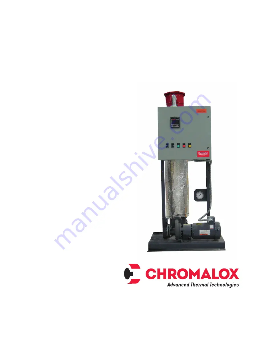
MOS Series Hot Oil System
PQ448-1
161-123417-032
September 201
8
Page 1: ...1 Installation Operation Manual MOS Series Hot Oil System PQ448 1 161 123417 032 September 2018 ...
Page 2: ...hase 60 cycles 50 thru 500kW In hazardous areas pipe surfaces could achieve temperatures high enough to cause auto ignition of the hazardous material pres ent Consult Article 500 of the National Elec tric Code for further information on the maxi mum allowable temperature for a specific application Unit Proportions Unit Size Dry Weight Lbs Width In Depth In Height1 In Flow Rate2 GPM Pressure2 TDH F...
Page 3: ...operation 2 The piping of the entire system should be arranged to minimize pockets where air may be trapped Manual air vents or bleeder valves should be pro vided in the system where air pockets may occur or where the flow of fluid may drop 3 Piping should be properly supported so pump can be removed without changing the position of the piping If piping moves when the pump is removed pump malfunct...
Page 4: ...essure of 2 to 3 psig 0 14 0 21 bar is maintained on pump Pump Motor The pump motor is a close coupled centrifugal pump rated for 650 F 343 C Pump and motor mounts should be checked and tightened if loosened during shipment DO provide for expansion and contraction of process piping and connections to the system Piping strains can cause pump and motor misalignment excessive wear on pump body bearin...
Page 5: ...um operating temperature is 650 F Maximum working pressure is 150 psi Horsepower requirement based on 0 85 specific gravity Maximum operating temperature is 650 F Maximum working pressure is 150 psi 100 150 kW Unit 7 5 hp 175 500 kW Unit 10 hp 50 75 kW Unit 5 hp ...
Page 6: ...ttage may be connect ed in series for operation at a higher voltage 5 The unit is completely wired The only wiring nec essary is to terminals L1 L2 and L3 in the control panel and the ground lug in the control panel Hazard of Electric Shock Disconnect all power before servicing the heat transfer sys tem 6 Jog the motor by pushing the push button marked START located on the front of the panel This ...
Page 7: ...valves 6 The temperature limiting device located inside the control panel should be checked to insure man ual reset buttons are in the closed position They should be set approximately 50 F 28 C higher than the process control during normal operation 7 Close control box door and turn circuit breaker on Start pump do not be alarmed if the pump is noisy during the initial start up operation since it ...
Page 8: ... Strainer Inlet Outlet Valves and Dedicated Fill Connections Ordering 2 or more of these options will require on site installation to avoid shipment damage The order of assembly starting at pump inlet should be gate valves strainer then fill connections A bolting kit with gaskets is provided for simple installation Please note that during operation the strainer should be checked as part of a regul...
Page 9: ...ns H System leaks at temperature and after cool down Expansion and contraction due to temperature has loosened connec tions Check all flange bolts and connections retighten and torque to manufacturer s specifications Wrong gasket materials Replace gaskets as necessary use spiral wound or Grafoil gaskets I Insufficient suction pressure 0 or vacuum pump noisy gauges vi brating discharge pressure low...
Page 10: ...ice Center 1 800 443 2640 Maximum Temperatures DO NOT attempt to operate any heat transfer system or heat transfer oil at temperatures higher than those recommended by the manufacturer Chromalox heat transfer systems are designed for a particular maximum temperature If you do not know this design temperature check with the Chromalox factory or consult the individual instruction sheet for that syst...