


- 8 -
© 2014 Chromalox
®
, Inc.
1-888-996-9258
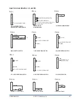
Figure Drawing Number
Model
Figure Model
1................
100A, 150A, & 200A 2-Leg Open Type
1................
100A, 150A, 200A, & 300A 1-Leg Open Type
2
................
100A, 150A, & 200A 3-Leg Open Type
3
................
300A 2-Leg Open Type
4
................
100A, 150A, 200A, 300A & 400A 1-Leg Touch-Safe
4
................
400A 1-Leg Open Type
5
................
100A, 150A, 200A, 300A & 400A 2-Leg Touch-Safe
5
................
400A 2-Leg Open Type
6
................
100A, 150A, 200A, 300A & 400A 3-Leg Touch-Safe
6
................
300A & 400A 3-Leg Open Type
7
................
550A & 650A 1-Leg Touch-Safe
7
................
550A & 650A 1-Leg Open Type
8................
550A & 650A 2-Leg Touch-Safe
8................
550A & 650A 2-Leg Open Type
9................
550A & 650A 3-Leg Touch-Safe
9................
550A & 650A 3-Leg Open Type
..................
800-1200 Amp units, consult factory
4
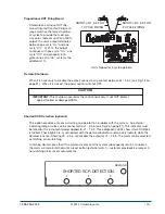
Installation
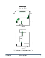
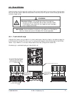
Please read all information in this section before beginning the installation of your MaxPac.
Installation of the MaxPac requires three steps:
1. Mounting
2. Power wiring
3. 120
or 230 Vac 50/60hz for instrument power. See 4.2.4, pg. 16.
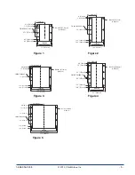
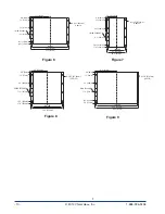
4.1 - Step 1: Mounting
Before mounting your MaxPac, please read the section titled “Before You Install’ on page 5 for a description
of an ideal environment for the unit’s operation.
The space required for mounting the MaxPac Power Pak depends upon the model. The table below refers to
the figures on the following pages. These figures illustrate the dimensions and mounting holes for the vari-
ous MaxPac Power Pak models. Please refer to these figures before mounting your unit.
IMPORTANT:
Please note that the figures on the following pages are
not drawn to the same scale.