1
PK520-1
0037-75533
December 2016
Installation & Operation Manual
ISC-Intellitrace Supervisory Controller
Page 1: ...1 PK520 1 0037 75533 December 2016 Installation Operation Manual ISC Intellitrace Supervisory Controller ...
Page 2: ...en 11 Adding Systems 12 Connecting Systems 13 Programming Editing 14 Setpoints Tab 14 Temperature Units 15 Navigation Note 15 Mass Setting 16 Apply Settings Globally 16 Synchronize Settings 16 Tuning Tab 19 Control Modes ON OFF PID Autotune 17 Soft Start Feature 18 I O Sensor Output Mapping Tab 18 Sensor Mapping 18 Output Mapping 20 System Tab 21 AutoCycle 21 Number of Current Samples 22 Configuri...
Page 3: ...ighted software proprietary notices and identifying informa tion the Extraction Software You may not alter or modify the Extraction Software You are not authorized to give to anyone else the per mission to modify the Extraction Software You may not reverse engineer decompile or disas semble any parts of the SOFTWARE PRODUCT except and only to the extent that such activity is expressly permitted by...
Page 4: ...Please read all instructions before operating your in telliTRACE ITLS ITAS ITLS EXT or ITAS EXT Control Panel To avoid electrical shock or injury always remove pow er before servicing a circuit Personnel working with or near high voltages should be familiar with modern methods of resuscitation Contact an area supervisor or safety personnel for more information HIGH VOLTAGE is used in the operation...
Page 5: ...ss is available at any control station on your network Additionally the intel liTRACE software package provides the owner with peace of mind with its electronic email of alarm events The intelliTRACE supervisory control is extremely ef ficient to set up and manage Intuitive Windows based system screens and global application of mass pa rameter value settings will have your system commis sioned in ...
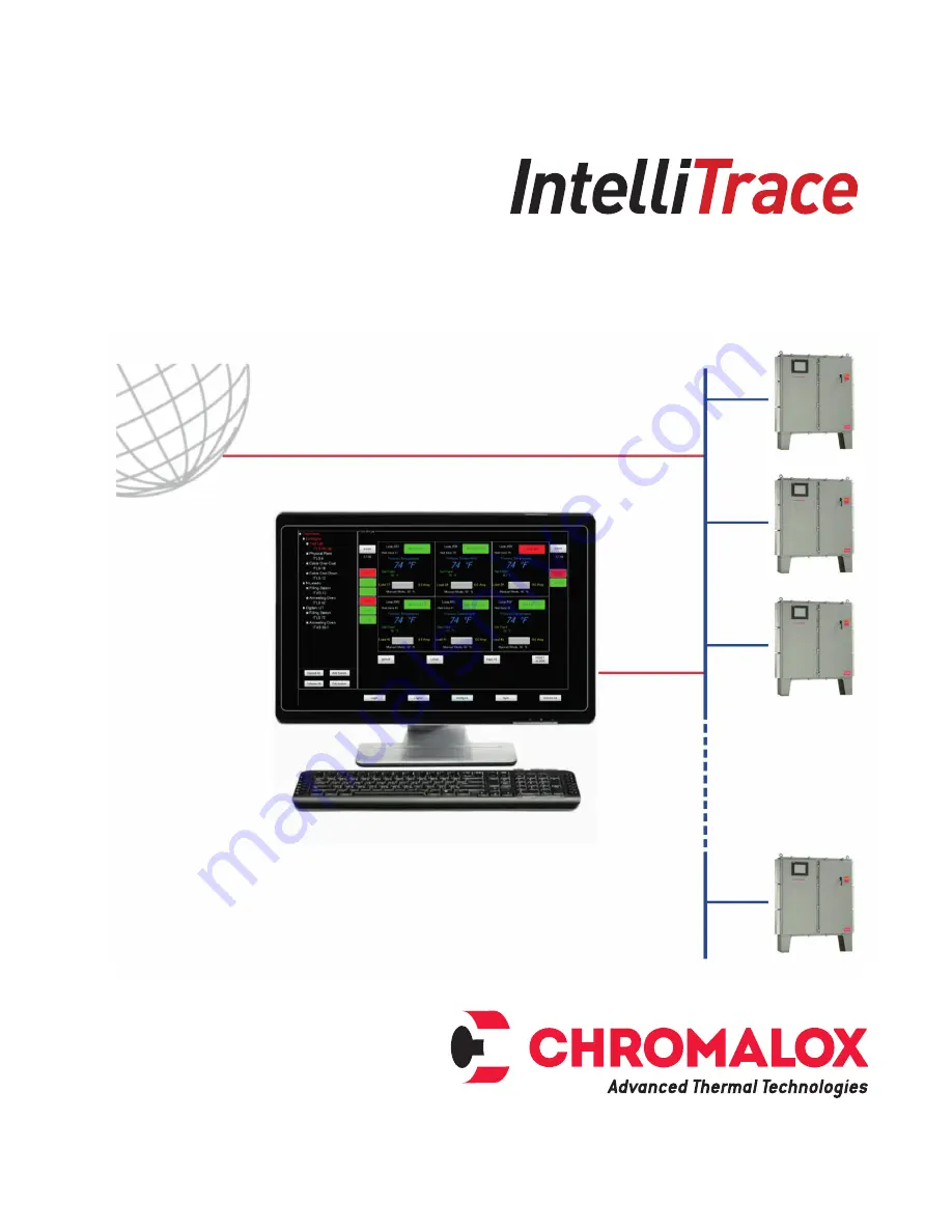
Page 6: ...le computer that is properly net worked or it may be embedded into an industrial PC that is mounted in its own enclosure Each individual intelliTRACE panel provides power management and or distribution to a maximum of 72 circuits The standard intelliTRACE system manages up to 128 intelliTRACE control panels Therefore 9 216 circuits of control are easily be managed by intelli TRACE controller The p...
Page 7: ...l Red Text indicates that there is a circuit within a certain area of your sys tem that is in the alarm state Four levels of your system are visible here 1 Company 2 Facility 3 Department 4 Individual Panel The System Tree detail may be varied depending on the resolution that you desire to view Discrete expanding and collapsing control is provided within each level via the and switches To fully ex...
Page 8: ...e also network connection and system utility but tons on the bottom Panel Name 6 Loop Navigation Button x2 Process Temperature Temperature Set point Alarm Status by 6 Loop Grouping 1 6 7 12 13 18 etc up to 67 72 Current Load see current samples Control Mode Output Quick Launch to Setup Logs Faults Pages Reset Alarm Login Logout of IntelliTRACE Network Quick Launch to Configure Page Quick Launch to...
Page 9: ...2GB RAM At least one unused 10 Base T or 10 100 Base T Ethernet port Color SVGA monitor 1024 x 768 minimum IntelliTRACE Supervisory Controller Installation Run the intelliTRACE program Setup Wizard Read and accept the agreement Complete installation of the intelliTRACE program by following the prompts Terminology Note When a Base Panel is combined with an Extension Panel this is often referred to ...
Page 10: ...ur convenience a table is provided with this manual to capture communication naming circuit setting and parameter value information See the sample below Figure 1 Planning Your IntelliTRACE Supervisory Controller System System Data Panel System System Edit Form Company Facility Site Department Area Panel Name Must be unique Number of Loops See COMMS on each Panel Name of Fac Port Number IP Address ...
Page 11: ... to gain access to the program The Login screen will appear requesting a password See Figure 3 Should you wish to logout of the system simply select the Logout button Initial factory set passwords and their pre defined accessibility rights for the below levels of Security are Level Title Code Accessibility Rights 4 Manager 999 All pages all passwords all Setpoints editing 3 Engineer 55 All pages E...
Page 12: ...3 The I P Address and the Modbus Address must match what was recorded from the respective Panel COMMS Page in Figure 4 Select the Save button when you are satisfied with this System Edit form data The intelliTRACE screen looks the same as it did when you first installed the program except for the entry of your new System or Panel See the new entry in both the System Tree Pane on the left and the P...
Page 13: ... Select the Connect All button at the bottom of the Main Screen This con nects all Panels Systems that have been properly saved to your network 3 Select the Connect to All Systems on Startup checkbox that is found on the Application Setup page This page is presented when you select the Configure button at the bottom of the Main Screen See Configuring Your System section for more detail If the sett...
Page 14: ...tch Enabled Disabled Output per mission upon GFEP Violation Output Control Mode behavior whether Auto matic AUTO or Manual Manual Output Control Load Percentage if enabled Loop Output Override Enable or Disable Each Loop Additionally there exists a Global Setting within the first Loop of each 6 Loop group Apply Globally Setting Definitions for each of the Setpoints Tab input Cells Customized Loop ...
Page 15: ...r to be a function of a PID Algorithm or ON OFF Control See Tuning Tab for selection Select Manual if you wish the Output to be driven by a pre determined Output Percentage Enter the desired output Disable Output Select this check box if you wish to turn off or disable this loop Apply Globally This allows the user to copy all of the settings or Loop Parameters from Loop 1 to all other available Lo...
Page 16: ... Figure 11 complete the input of the parame ters and then select the Apply Globally button to mirror these settings across all loops within that panel system Synchronize Settings The intelliTRACE Supervisory Controller also offers a feature which allows the user to apply the settings from one system panel to any or all of the remaining systems panels on the network Press the Sync button at the bot...
Page 17: ...at demand is removed The output is ON until the Process Temperature equals the upper limit of the Deadband The output is then turned off until the Process Temperature falls below the lower limit of the Deadband At this point the cycle repeats See Chart 1 Select PID if you desire PID Control of the heaters The owner may input his her Integral Derivative and Propor tional Band parameters in the appr...
Page 18: ...troller will facilitate the customizable I O Mapping feature found on the ITLS ITLSC1D2 type Heat Trace panels This is only available if the I O Mapping feature on the panels themselves is enabled This becomes a very powerful and desirable feature when the owner needs added flexibility in controlling the circuit outputs beyond the standard single sensor input This is not available in the ITAS or I...
Page 19: ...mbining Sensing Types The owner may need to have multiple Line and or Ambient Sensing control scenarios occurring simultaneously For example these may be occurring simultaneously 1 Circuits 1 2 3 4 5 are all controlled by a single RTD Sensor 1 that is sensing the ambient tempera ture Ambient Sensing 2 Circuit 6 is controlled by Sensor input 2 which is strapped to a process pipe Line Sensing Sensor...
Page 20: ... the Average Output demand value of all of the Outputs that are mapped to that single Circuit Multiple Output Mapping A single output demand value may be used independently or combined with other output demand values to con trol more than one circuit For Example The average output demand value of circuits 1 3 5 is used to control Circuit 1 while simultaneously the maximum Output demand value of Ci...
Page 21: ...Feature select an AutoCycle Interval greater than 0 hours The AutoCycle Feature is disabled when the AutoCycle Interval equals 0 hours On a sequential circuit basis the AutoCycle feature periodically monitors system performance at intervals of 1 999 hours The minimum and maximum values for Current Load GFEP and Temperatures are stored Once the new high or low value is attained the old value is ove...
Page 22: ...nt samples increases the accuracy of the current sample reading However this will increase the time required to execute the circuit reading process Likewise reducing the number of current samples decreases the current reading accuracy How ever the survey process is completed faster Therefore one must choose whether accuracy of this reading or the frequency of this reading is most important The min...
Page 23: ...rm Behavior Use audible sound when alarm occurs When engaged an audible beep will occur at the intelliTRACE Supervisory Controller Send email when alarm occurs when selected an email will be sent to the provided address when an alarm event occurs Select which types of alarms should be sent Choose which alarms types are valid for an email alert message Security Revise all four levels of password se...
Page 24: ...in Screen is selected See Figure 18 This log may be saved to a file To accomplish this select the Save button on the right side of the Log Form You will be prompted with a Save As window Choose the destination of your choice See Figure 19 The Event Log file will be saved as a CSV comma separated value type Text txt file This will be important if it is to be viewed or manipulated in Microsoft Excel...
Page 25: ...dow Up to three Alarm Conditions can be illustrated for any single loop on the Main Menu Screen 2 One may view the status of all fault conditions by selecting the FAULTS button located at the bottom of any screen To navigate to the desired 6 Loop grouping one must press the Loop Navigation buttons found in the upper right or left corner of any screen See Figure 20 Clearing Alarms Except for a Comm...
Page 26: ...m Yes Yes Output will go to 0 OFF until alarm is reset HI CURRENT LOAD on Faults Screen Sensed Load Current Hi Cur rent Setpoint Output will switch to Manual Mode Alarm will be cleared automatically when sensed Load Current Hi Current Setpoint LO CURRENT LOAD on Faults Screen Sensed Load Current Lo Cur rent Setpoint No change Alarm will clear automatically when Sensed Load Current Lo Current Setpo...
Page 27: ...led Enabled Disabled Wiring Considerations The maximum distance between ITLS panel and router can be 100m If this distance needs to be ex tended it would be necessary to utilize an inline repeater Cable that should be used is CAT5 RJ45 Ethernet cable The HMI display has 1 Ethernet port on the back of the display see photo below Insert one end of the Ethernet cable into the HMI and the other end in...
Page 28: ...967 3800 1347 Heil Quaker Blvd LaVergne TN 37086 Phone 615 793 3900 Customer Service Hotline 1 800 443 2640 For application questions you can 1 Call one of our application engineers for personal assistance at 1 888 996 9258 2 Visit the technical reference section of our website at www chromalox com for downloadable manuals in PDF format Limited Warranty Please refer to the Chromalox limited warran...