


6
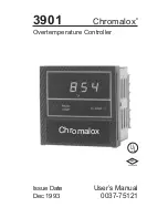
Chromalox 3901 User’s Manual
Important
Wiring
Information
To insure that the 3901 controller performs
optimally, it is imperative that you read this section
and become familiar with “Good Wiring Practices”
critical to eliminating electrical noise. Failure to
follow good wiring practices can result in poor
temperature measurement and ineffective high limit
control.
Snubbers
Snubbers should be used to protect the controller
from electrical noise generated by inductive loads
such as motors, solenoids, coils and relays operating
near the 3901 controller. The recommended snubber
is a .1uf capacitor (600 Vdc rating) in series with a
100 ohm resistor and is available from Chromalox
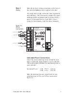
(PCN 314448). The wiring diagram in this manual
illustrates the snubber connection.
Good
Wiring
Practice
Read and follow these Good Wiring Practices when
connecting this and any other controller:
1. Do not run sensor leadwires and power leads
together in the same conduit or wire tray.
2. When planning the system wiring, be sure to
consider the importance of separating wiring into
functionally similar bundles—i.e. power leads,
sensor leads, output signal lines, etc. If the power
leads and sensor leads must cross, they should cross
at a 90
°
angle to each other (perpendicular).
3. Locate all sources of noise in your system—
motors, contacts, solenoids, etc. Then design your
system such that wiring is separated as far as
possible from these noise sources.
4. Shielded, twisted wire should be used for the
control circuit signals if they are run in parallel with
other control circuit signal wires, or if they are run
distances greater than 2-3 feet.
5. To protect against noise, use shielded cables for all
low power signal lines.
6. Additional information on good wiring practices is
available from IEEE, 345 East 47th St., NY, NY
10017. Request IEEE Standard No. 5128-1982.