


8
Chromalox 3901 User’s Manual
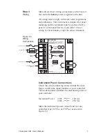
Sensor Input Connections
The thermocouple input is connected at terminals 7
(+) and 8 (-) as indicated by the wiring decal on the
back of the controller. The table below shows typical
color coding for the thermocouples used with this
controller:
T/C Type
J
K
Material
Plus(+)
Minus (-)
Iron/Constantan
White
Red
Chromel/Alumel
Yellow
Red
If shielded thermocouple wire is used, the shield
must be grounded at one end only, preferably at the
case ground (CASE GND) of the controller.
If thermocouple extension wire is required, it must
be the same type of extension wire as the
thermocouple (for example, if the thermocouple is
Type J, the extension wire must be Type J).
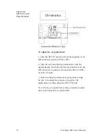
Alarm Output Connection
The alarm relay output connections are made at
terminals 1 and 2. Make the wiring connections as
shown in Figure 2.4, using the recommended
snubber circuit as discussed on page 6.
Remote Alarm Reset Connection
Terminals 3 and 4 are provided for connection of a
remote, normally-open reset switch. Make the reset
switch connection as shown in Figure 2.4.