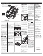
Parts and Module Replacement
CP42LH Service Manual
70
020-101686-03 Rev. 1 (08-2016)
9. Disconnect the J1 connector.
10. Remove the infrared emitter module.
Color sensor module
Estimated replacement time: 4 minutes
1. Remove the
2. Remove the 2 screws securing the color sensor module to the projector.
3. Remove the color sensor module.
Remote temperature sensor module light engine
compartment
Temperature sensors are located in the optical compartment, the air intake, the prism assembly,
and each of the DMDs. These sensors monitor the projector components to make sure they do not
exceed the recommended operating temperatures.
Estimated replacement time: 5 minutes per sensor
1. Remove the
2. Remove the
Light engine fans (fans 1, 2, 3, and 4)
3. Disconnect the harness from the required remote temperature sensor module (RTSM).
4. Remove the screws securing the RTSM.
Remote temperature sensor module optical compartment
1. Open the
2. Disconnect the harness from the required remote temperature sensor module (RTSM).
3. Remove the screws securing the RTSM on the diffuser, integrator, and fiber receiver.
Card cage assembly
Estimated replacement time: 14 minutes
The card cage assembly is beside the light engine compartment.
1. Remove the
2. Remove the 4 screws securing the bracket holder to the card cage and top tube and remove it.
3. Loosen the captive thumb screw securing the card cage to the bottom of the chassis.
4. Disconnect the light engine quick disconnect (LEQD) board from the backplane.Disconnect the
LEQD from the backplane.Disconnect the card cage intake fan harnesses 9, 10, 11, and 12 from
the inline connectors.
5. Disconnect these harnesses from the active backplane: P7, P8, P10, and P13.P13.
6. Lift the card cage up and out.


