background image

B

Lock

C

Turn to adjust height

2. Extend or retract the feet.
3. When the adjustment is correct, tighten the lock nut.

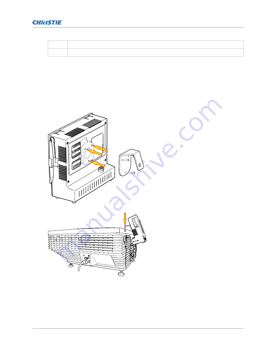
Installing the touch panel controller

Attach the touch panel controller to the projector.

1. Attach the mounting bracket to the touch panel controller using the three M4 screws and the 3

mm hex driver provided.

2. Slide the mounting bracket into the bracket support.

3. Connect the connector from the touch panel controller to the port on the side of the projector.

Installing and setting up

CP2208-LP Installation and Setup Manual

15

020-102152-03 Rev. 1 (05-2017)

Copyright 

©

 2017 Christie Digital Systems USA Inc. All rights reserved.

Summary of Contents for CP2208-LP

Page 1: ...Installation and Setup Manual 020 102152 03 CP2208 LP...

Page 2: ...t where the product is designed for outdoor use problems or damage caused by use of the product outdoors unless such product is protected from precipitation or other adverse weather or environmental c...

Page 3: ...g the projector 13 Adjusting tilt and leveling the projector 14 Installing the touch panel controller 15 Installing the lens 16 Connecting power 18 Turning the projector on 19 Logging on to the projec...

Page 4: ...test patterns 32 Turning a test pattern on or off 32 Displaying a full screen test pattern 32 Specifications 33 Physical specifications 33 Power specifications 33 Environmental specifications 34 Displ...

Page 5: ...ocedures Hot surface hazard To avoid personal injury allow the product to cool for the recommended cool down time before performing maintenance or service Pinch hazard To avoid personal injury keep ha...

Page 6: ...und Indicates the presence of an earth ground Additional hazard labels Indicates a light hazard Do not look directly into the lens The extreme high brightness can cause permanent eye damage RG3 IEC 62...

Page 7: ...the beam must be permitted RG3 IEC 62471 5 2015 PERMANENT TEMPORARY BLINDNESS HAZARD Operators must control access to the beam within the hazard distance or install the product at the height greater t...

Page 8: ...ded the following could result in minor or moderate injury FIRE HAZARD Do not use a power cord harness or cable that appears damaged FIRE OR SHOCK HAZARD Do not overload power outlets and extension co...

Page 9: ...t number Zone A m 1 2 1 72 1 0 69 DLPCine zoom lens 108 494108 XX 0 to 1 6 1 33 2 1 1 0 69 DLPCine zoom lens 108 495109 XX 0 to 2 2 1 62 2 7 1 0 69 DLPCine zoom lens 108 496100 XX 0 to 3 0 2 09 3 9 1...

Page 10: ...r Zone A m 2 09 3 9 1 0 69 DLPCine zoom lens 108 497101 XX 0 to 1 9 Safety precautions CP2208 LP Installation and Setup Manual 10 020 102152 03 Rev 1 05 2017 Copyright 2017 Christie Digital Systems US...

Page 11: ...08 LP User Manual P N 020 102150 XX Projector components front Learn about the components on the front of the projector A Touch panel controller TPC A touch sensitive screen used to control the projec...

Page 12: ...enses is available in the projector specifications on page 33 G Lens surround H Top skin I Air filter Projector components rear Learn about the components on the back of the projector A Service access...

Page 13: ...the projector in the location where it will be used Warning If not avoided the following could result in death or serious injury A minimum of four people or appropriately rated lift equipment is requi...

Page 14: ...the projector slightly off center and use lens offset to center the image on the screen Adjusting tilt and leveling the projector To ensure optimum performance install the projector so it is centered...

Page 15: ...nting bracket to the touch panel controller using the three M4 screws and the 3 mm hex driver provided 2 Slide the mounting bracket into the bracket support 3 Connect the connector from the touch pane...

Page 16: ...mp on the front of the projector to the open position with a hex key 3 Position the lens so the lens retaining ring mounts align with the lens mount 4 Remove the lens caps from the front and rear of t...

Page 17: ...tely with the projector 7 Lock the lens assembly in place with a hex key 8 Replace the lens surround Installing and setting up CP2208 LP Installation and Setup Manual 17 020 102152 03 Rev 1 05 2017 Co...

Page 18: ...r and main power supply plug must be easily accessible for disconnecting the product from the power source Caution If not avoided the following could result in minor or moderate injury Only Christie q...

Page 19: ...ned on using the touch panel controller TPC Warning If not avoided the following could result in death or serious injury SHOCK HAZARD Do not attempt operation if the AC supply is not within the specif...

Page 20: ...irewall is unbroken the projector is unaltered and to tap the marriage button on the card cage faceplate 1 On the touch panel controller TPC log on to the projector on page 19 with marriage permission...

Page 21: ...d 1 On the touch panel controller TPC tap Menu Advanced Setup Lens Setup 2 From the Primary Lens list select a lens 3 In the Intelligent Lens System area tap Full Calibration 4 Tap Yes Installing and...

Page 22: ...minus icons until the image fits your screen 9 In the Focus area tap the left and right focus icons until the test pattern details are in focus When your adjustment is complete the words and lines in...

Page 23: ...pears distorted and resembles a trapezoid If the image suffers from slight keystone effect it can be corrected with electronic cropping If the keystone effect is severe complete a horizontal or vertic...

Page 24: ...een image vibration After adjusting boresight evaluate the on screen image vibration and re adjust if needed 1 Remove the lens surround 2 Display the DC2K Boresight test pattern on page 32 This test p...

Page 25: ...resight cap screw E 8 To focus the position III boresight guide adjust the top boresight cap screw F Turning the screws in small amounts 1 4 to 1 8 of a turn allows you to make precise adjustments Adj...

Page 26: ...s corrected and does not show the native output 1 On the touch panel controller TPC tap Menu Advanced Setup MCGD File Setup 2 To display the white test pattern in the white area of the chromaticity im...

Page 27: ...he specified value prior to color correction as color correction decreases light output 7 Tap Advanced Power Adjust 8 Individually adjust the Yellow and Blue power settings returning to the MCGD File...

Page 28: ...ntent to the projector Projector connections Item Description A Indicates the status of the regulator A solid blue LED indicates the regulator is enabled If the LED is not illuminated the regulator is...

Page 29: ...error A flashing red LED indicates the PIB is not installed correctly If the LED is not illuminated the PIB is inactive ICP The LED is green when the ICP is operating correctly A red LED indicates a c...

Page 30: ...unication settings if any network information changes 1 On the touch panel controller TPC log on to the projector on page 19 with administrator or service permissions 2 Tap Menu Administrator Setup Co...

Page 31: ...to an audio processor See the documentation included with the audio processor for detailed set up instructions 2 To play encrypted content a Install an Integrated Media Block IMB b Connect the projec...

Page 32: ...n the bottom right corner Turning a test pattern on or off Test patterns are available to assist with the configuration of the projector and to diagnose any issues that may occur 1 In the touch panel...

Page 33: ...bs Shipping weight 101 kg 223 lbs Touch panel controller W x H x D 195 mm 7 68 inches x 148 mm 5 83 inches x 44 4 mm 1 75 inches Power specifications Learn the power requirements for the projector AC...

Page 34: ...ent Item Description Temperature 15 C to 35 C 59 F to 95 F from 0 500 meters 15 C to 28 C 59 F to 82 F from 500 3000 meters Humidity non condensing 20 to 85 Altitude 0 3000 meters Non operating enviro...

Page 35: ...the control signal compatibility for the projector Ethernet port Interface 10Base T 100 Base TX Connector Female RJ 45 Bit Rate 10 Mbps or 100 Mbps half and full duplex RS232 PIBS1 Interface TIA 232...

Page 36: ...ommunication Interface with Projector 10 1000Base T Ethernet Power Requirement 1 02 A maximum at 24 VDC 10 Interface Connector 12 pin Circular connector push pull Accessories Learn what accessories ar...

Page 37: ...electrical and electronic equipment and the applicable official amendment s EU Regulation EC No 1907 2006 on the registration evaluation authorization and restriction of chemicals REACH and the applic...

Page 38: ...Seoul ph 82 2 702 1601 Japan Tokyo ph 81 3 3599 7481 India ph 91 080 6708 9999 Germany ph 49 2161 664540 France ph 33 0 1 41 21 44 04 Eastern Europe and Russian Federation ph 36 0 1 47 48 100 China Sh...

Reviews: