background image

NO:2021.04

Standard: IEC/EN 60947-2

GB/T 14048.2

User Instruction

NM1 Series
Moulded Case Circuit Breaker

Summary of Contents for NM1 Series

Page 1: ...NO 2021 04 Standard IEC EN 60947 2 GB T 14048 2 User Instruction NM1 Series Moulded Case Circuit Breaker ...

Page 2: ...ited from touching the conductive part when the product is operating When the product is being installed or maintained the power must be switched off Do not install it in a place where gaseous media can corrode metals and damage insulation In order to avoid dangerous accidents the installation and fixation of the product must be carried out in strict accordance with the requirements of the user in...

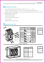
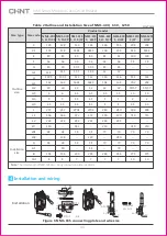
Page 3: ...stallation category Ⅲ f IP degree IP30 g Rated insulation voltage Ui 800V Inspection and Test NM1 Series Moulded Case Circuit Breaker Smin 25min 25min 20min Figure 1 Inspection Model NM1 63H NM1 125 NM1 250 NM1 400 NM1 630 NM1 800 NM1 1250 NM1 63S M4 30 M4 45 M6 75 M6 90 M8 40 2P 2 2 3P 4 4 4 4 4 4 4 4 4P 4 4 4 4 4 4 4 Unit mm NM1 63 NM1 125 NM1 250 NM1 400 NM1 630 NM1 800 NM1 1250 Model S 50 100 ...

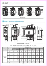
Page 4: ... G A A W2 W1 W1 W1 L2 G1 6X d Φ 3P 4P Undervoltage release Table 1 Outline and Installation Size of NM1 63 125 250 Size type NM1 63S NM1 63H NM1 125S NM1 125 H R NM1 125 H 2P NM1 250S NM1 250 H R NM1 250 S 2P Product model Size code Outline size C E F G G1 H H1 H2 85 48 23 14 6 5 71 91 19 85 48 23 14 6 5 80 100 28 85 51 23 17 5 7 5 68 86 24 85 51 23 17 5 7 5 86 104 24 85 51 23 17 5 7 5 86 102 24 1...

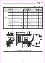
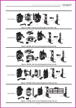
Page 5: ... 117 4 5 4 7 155 255 136 90 30 120 65 30 130 5 4 5X6 4 7 155 255 136 90 30 120 30 130 5 4 5 6 4 7 150 250 130 30 65 129 4 5 3 5 5 5 165 362 144 105 35 140 35 126 5 3 5 5 5 165 362 144 105 35 140 75 35 126 5 3 5 5 5 165 362 144 35 75 126 5 Installation size Table 1 Continued Figure 5 NM1 400 630 800 1250 3P H2 H H1 max H5 H4 H3 22 E F A G G1 W1 W1 W 4XΦd 22 A A1 W1 W1 W1 W2 C C1 B L2 L L1 6XΦd 4P F...

Page 6: ...6 184 5 89 66 40 5 15 5 112 164 5 42 6 5 3 5 4 5 270 5 472 234 58 240 58 58 200 7 136 204 81 66 45 12 116 168 42 4 5 5 8 280 490 243 210 70 70 243 7 136 204 81 66 45 12 116 168 42 4 5 5 8 280 490 243 70 280 70 70 243 7 204 316 100 78 141 202 55 57 19 2 4 5 406 710 210 70 70 375 10 204 345 5 100 78 141 202 55 57 19 2 4 5 406 715 210 70 70 375 10 Installation size Table 2 Outline and Installation Si...

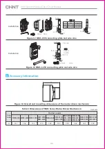
Page 7: ...21 38 6 M8 6H Cross area s b c 16 C 4 10 X 13 a 6 b 12 Φ5 5 b 12 Φ5 5 a 6 M8 16 8N m Φ8 2 18 16 40 5 25 5 M8 6H 7 5 14 5 21 5 4 R6 R6 C 4 10 X 13 a 7 b 15 b 15 Φ8 5 Φ8 5 a 7 Cross area s b c 50 M8 16 10N m 23 15 5 27 R8 R8 39 9 4 57 20 M8 6H Φ8 8 10 X 13 a 7 a 7 Φ8 5 Φ8 5 b 22 b 22 C 6 Cross area s b c 120 M10 30 22N m 27 Φ14 43 12 Φ10 5 8 27 8 Φ14 43 Φ10 5 16 5 X 18 Φ10 5 Φ10 5 a 12 b 30 a 12 b 3...

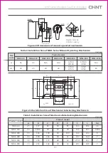
Page 8: ...1250 connecting plate and wire size Installation M12 60 30N m C 15 16 X 18 2 Φd 12 32 45 Cross area 2 s 400 10 2 article M12 35 28N m 2 Φ14 72 44 10 C 12 19 X 21 Φ14 b 44 Φ14 b 44 s b c 240 s b c 250 s b c 480 s b c 500 a 12 a 12 Double Single Wire Copper bar 5 Accessory Information Figure 14 Overall and mounting dimensions of the motor driven mechanism Size code Product model H 157 166 152 170 18...

Page 9: ...8 Table 4 Installation Size of NM1 Series Manual Operating Mechanism Unit mm 3P 18 4P 20 3P 20 4P 18 Figure 16 Installation Size of Mechanical Interlocking Mechanism Switch A Switch B B F D E L A C A 8XΦd A B C D E F L Φd Product model Product model NM1 63 NM1 125 NM1 250 NM1 400 NM1 630 NM1 800 Table 5 Installation Size of Mechanical Interlocking Mechanism Unit mm 25 30 35 44 58 70 117 130 5 126 ...

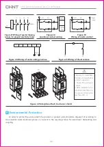
Page 10: ... of under voltage release Figure 21 Wiring of Shunt release 1 Be sure to install flash barriers or shield before product operation 2 Check if the wiring is correct 3 After installation the insulation resistance to the ground shall not be less than 10m Ω Figure 22 Interphase flash barrier or shield 6 Environmental Protection In order to protect the environment the product or product parts should be...

Page 11: ...QC PASS Test date Please see the packing ZHEJIANG CHINT ELECTRICS CO LTD NM1 Series Moulded Case Circuit Breaker IEC EN 60947 2 GB T 14048 2 PD1 Check 15 09 NM1 Series Moulded Case Circuit Breaker ...

Page 12: ...d Case Circuit Breaker User Instruction Zhejiang Chint Electrics Co Ltd Add No 1 CHINT Road CHINT Industrial Zone North Baixiang Yueqing Zhejiang 325603 P R China E mail global sales chint com Website http en chint com ...

Reviews: