


チコーエアーテック株式会社
Copyright CHIKO AIRTEC CO., LTD. 2009
13
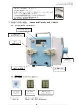
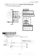
5.4
隔操作と本体操作について
Remote operation and operation from main body
遠隔操作で
ON/OFF
する場合は、④と⑧を短絡させておきます。
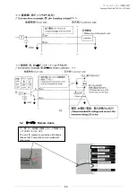
①を短絡
The wire [1] is short-circuited.
→
ON
①を短絡しない
The wire [1] is not short-circuited
→
OFF
(「各線の色と信号について」の表を参照ください)
Short-circuit the wires [4] and [8] each other when turning ON and OFF the dust collector by remote
operation.
(Refer to the table in
“Color and signal of each wire”)
本体操作で
ON/OFF
して信号を取り出す場合は、④と⑧を短絡させないでください。
「
5.3
各線の色と信号について」の説明に従い、必要な出力信号を取り出して下さい。
Do not short-circuit the wires [4] and [8] each other when transferring signals by turning ON and
OFF the dust collector from the main body.
Transfer required output signals in accordance with the explanation in
“5.3 Color and signal of each
wire
”
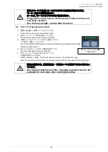
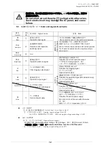
遠隔操作で運転中に能力レベルを変更する場合は、
本体
AT
パネルの
ON
を押しながら
Lo, Hi
で変更してください。
Change with Lo/Hi switch pushing the ON switch of main body AT panel when
you change the suction level during the driving with remote controller.
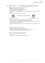
能力レベルの記憶
The memory of the capacity level
本体パネルの
Lo/Hi
ボタンで能力レベルを記憶しておく事
ができます。
The capacity level is memorized by the Lo/Hi switch of AT panel.
ON
OFF
①を短絡する
The wire [1] is short-circuited.
①を短絡しない
The wire [1] is not short-circuited