background image

Ch ief Manufacturing, a d ivision of Milestone AV Technologies

8401 Eagle Cr eek Pa rkway, Savage, MN  55378

P: 800 .582.6480 / 952.894.62 80  F: 877.894.6918 / 952.894.6918

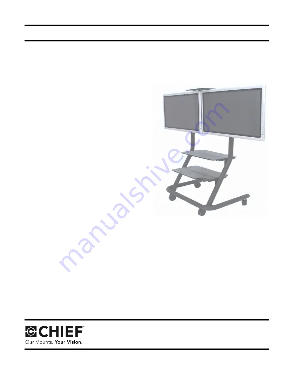
Plasma Presenters Dual Display
Video Conferencing Cart (PPD-Series)

BEFORE YOU BEGIN

CAUTION:  To prevent damage to the cart, which could affect or void the Factory warranty, thoroughly
study all instructions and illustrations before you begin to install or operate the unit.  Pay particular atten-
tion to the “Important Warnings and Cautions” on Page 2.

The maximum weight to be installed on the PPD is 200 pounds (90.72 Kg).

If you have any questions about this assembly, contact Chief Manufacturing at 1-800-582-6480 or 952-894-6280.

Chief® and ClickConnect™ are trademarks of Milestone AV Technologies. All rights reserved.

I N S T A L L A T I O N   I N S T R U C T I O N S

The PPD is a highly functional video conferencing solu-
tion. The cart provides agile mobility for two Large Flat
Panel Displays, side-by-side, with a combined weight of
up to 200 pounds. Optional equipment shelves and video
conferencing accessory shelves can be easily added for
a complete system.

Using Chief’s exclusive ClickConnect™ Mounting Sys-
tem for easy installation, the cart provides stable mount-
ing, quick release and optional security. Additionally, its
streamline shape eliminates trip hazards and allows the
display to roll smoothly up to a conference table

Large swivel casters with lock brakes, pitch adjustment,
and cable management make the cart user friendly.

8809-000004 Rev E

©2008 Milestone AV Technologies

www.chiefmfg.com

05-08

Summary of Contents for PPD Series

Page 1: ...80 Chief and ClickConnect are trademarks of Milestone AV Technologies All rights reserved I N S T A L L A T I O N I N S T R U C T I O N S The PPD is a highly functional video conferencing solu tion The cart provides agile mobility for two Large Flat Panel Displays side by side with a combined weight of up to 200 pounds Optional equipment shelves and video conferencing accessory shelves can be easi...

Page 2: ...uctions WARNING Do not attempt to hang the plasma displays onto the cart alone Always use two people to mount each display WARNING Always park the cart on a level surface The locking wheels of the cart are not designed to hold the cart on an inclined surface WARNING Do not use the cart to transport your plasma displays on ramps or steep angles The cart is designed to move on smooth flat surfaces C...

Page 3: ...ge 4 and PARTS on page 4 Carefully inspect the parts for shipping damage If any damage is apparent call your carrier claims agent and do not continue with the assembly proce dure until the carrier has reviewed the damage OPTIONAL ACCESSORIES Acrylic Shelf Video Conferencing Shelf TOOLS REQUIRED FOR INSTALLATION 7 16 and 3 4 wrench Allen wrenches Socket set with extension NOTE Other tools may be re...

Page 4: ... 28 30 PLUG Cap hard plastic use with base 2 140 SCREW Cap Button head 5 16 18 x 3 4 6 40 PLUG Cap slip on vinyl use with legs 2 150 WASHER 1 4 2 50 PLATE Face 2 160 WRENCH Allen 3 16 Not Shown 1 60 FACEPLATE Sides 4 70 HEAD Mounting PPC Tilt Head 1 80 BRACKET Dual Screen Mounting 1 90 SPREADER Head tilt viewed from inside 2 100 BASE With corner supports 1 110 LEG Left 1 160 120 110 100 10 20 130 ...

Page 5: ...Installation Instuctions PPD Series 5 PARTS CONT D 50 70 80 130 140 60 ...

Page 6: ...s 150 and two 1 4 x 1 2 screws 130 c Install cap plugs 30 in base see Figure 3 d Install cap plugs 40 on top of left leg 110 and right leg 120 See Figure 4 4 Using two 1 4 20 x 5 8 button head screws 130 one on each side secure the mounting head 70 to the top of the legs 110 and 120 of the cart see Figure 4 5 Using four 1 4 20 x 5 8 button head screws 130 two on each side secure two tilt head spre...

Page 7: ...1 4 20x5 8 button head cap screws 130 See Figure 5 7 Using six 5 16 18X3 4 screws 140 secure the dual screen mounting bracket 80 to the tilt mounting head 70 see Figure 6 Dual Loosen Screws Loosen Screws Tilt Head Spreader 0 to 7 5 Degrees 80 Mounting Bracket 90 Tilt Mounting Head 70 Screen 5 16 18 Screws 140 Tilt Mounting Dual Screen Mounting Bracket 80 Head 70 Figure 5 Adjust Tilt Mounting Head ...

Page 8: ...easurement found in Step 1 and the faceplate 50 as a template measure from the cen ter of the dual screen mounting bracket 80 to find the correct mounting holes for your application see Figure 7 3 Secure each face plate 50 using four 1 4 20x5 8 screws 130 see Figure 8 Mounting Bracket 80 Dual Screen Figure 7 Dual Screen Mounting Bracket Head Measurements Face Plates 50 Figure 8 Dual Mounting Head ...

Page 9: ...ensure recessed area of mounting buttons are properly seated in lower area of mounting holes and ClickConnect mechanism has engaged See Figure 9 and See Figure 10 Figure 9 Hang Display NOTE Holes are provided in the faceplate for use with a padlock or similar locking device if desired In addition the pin and nut may be removed from the upper holes and moved to the lower holes for use as a more per...

Page 10: ...10 Installation Instuctions PPD Series ...

Page 11: ...Installation Instuctions PPD Series 11 ...

Page 12: ...12 Installation Instuctions PPD Series ...

Reviews: