background image

I N S T A L L A T I O N   I N S T R U C T I O N S
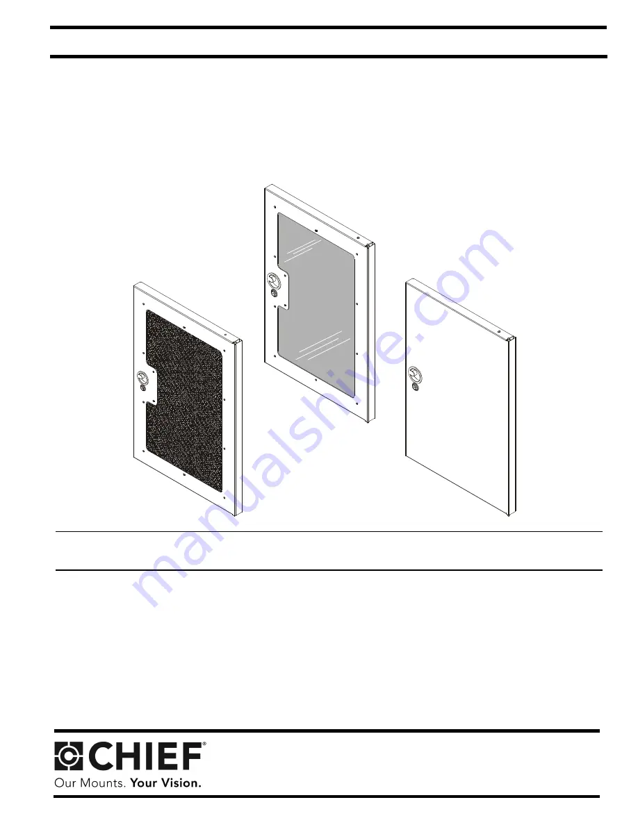
NS1D12F

NS1D12P

NS1D12S

S1 Racks Doors

Spanish Product Description
German Product Description

 Portuguese Product Description

 Italian Product Description

Dutch Product Description

French Product Description

NS1D12-20-28-36-41

Summary of Contents for NS1D12F

Page 1: ... C T I O N S NS1D12F NS1D12P NS1D12S S1 Racks Doors Spanish Product Description German Product Description Portuguese Product Description Italian Product Description Dutch Product Description French Product Description NS1D12 20 28 36 41 ...

Page 2: ...e possibility of serious injury or death if you do not follow the instructions CAUTION A CAUTION alerts you to the possibility of damage or destruction of equipment if you do not follow the corresponding instructions WARNING Failure to read thoroughly understand and follow all instructions can result in serious personal injury damage to equipment or voiding of factory warranty It is the installer ...

Page 3: ...2 20 28 36 41 3 TOOLS REQUIRED FOR INSTALLATION PARTS 2 7 16 OR OR A 1 Door B 1 Door catch C 1 Top door support E 2 1 4 20 x 5 8 F 2 1 4 20 Perforated Solid Plexiglass NS1D12P shown NS1D12F shown NS1D12S shown Lower door support D 1 ...

Page 4: ...MPORTANT If the door is to be attached with the pull ring handle on the right side the two nuts and grounding wire already installed on the door must be removed and reinstalled on the opposite end of the door before the door is installed The grounding wire should be on the BOTTOM of the installed door See Figure 3 Figure 3 4 Rotate two spring handles one at bottom and one at top on inside of door ...

Page 5: ...end into door supports and re latch spring handle 8 Determine location for door catch B by matching up handle cut out in door with correct position on rack See Figure 6 Figure 6 9 Add door catch B to rack rail using two 1 4 20 x 5 8 screws E and two 1 4 20 lock nuts F See Figure 7 Figure 7 10 Loosen screw in lower door support attach door grounding wire and tighten screw to finish connection See F...

Page 6: ...NJURY Grounding must be installed by qualified personnel using a UL Recognized No 12AWG Green and Yellow grounding wire connected to grounding lug on rack inside view of door Grounding screw and nut installed at factory affixed adjacent to grounding terminal Earthing symbol IEC 60417 No 5019 Location of grounding lugs ...

Page 7: ...Installation Instructions NS1D12 20 28 36 41 7 ...

Page 8: ...31 0 495 580 852 F 31 0 495 580 845 Asia Pacific A Office No 1 on 12 F Shatin Galleria 18 24 Shan Mei Street Fotan Shatin Hong Kong P 852 2145 4099 F 852 2145 4477 NS1D12 20 28 36 41 Installation Instructions Chief Manufacturing a products divi sion of Milestone AV Technologies 8821 002016 Rev02 2012 Milestone AV Technologies a Duchossois Group Company www chiefmfg com 06 12 ...

Reviews: