background image

CHIEF MANUFACTURING INC. 

8805-000137 (Rev. B) 

1-800-582-6480

  952-894-6280 FAX 952-894-6918 

2005 Chief Manufacturing 

8401 EAGLE CREEK PARKWAY, STE. 700 

www.chiefmfg.com


SAVAGE, MINNESOTA 55378  USA 

11/05 

I N S T A L L A T I O N       I N S T R U C T I O N S  

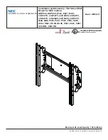
MEDIUM FLAT PANEL DISPLAY TILT MOUNT  

MTR Series


The MTR Series tilt mount accommodates medium flat 
panel displays weighing up to 100 lbs (45.36kgs). 

The teardrop holes in the mount allow for quick 
connect/disconnect of the display, thus simplifying 
installation and maintenance processes.  

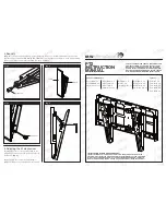
The top and bottom mounting brackets are adaptable to 
single wood stud mounting or dual wood studs that are 
16” on center.  

The display can be pulled and tilted into any position in 
the zero-to-15 degree tilt range and remain stationary. 
When fully retracted, the mount depth is 1.54 inches. 

After installing the display on the mount, the screen can 
be locked in place using the convenient locking flag.  
A padlock can be used on the latching flag for added 
security. 

The mount is concealed behind the display, making it a 
low profile wall mount. 


MTR Series 


! IMPORTANT:

  If the installation of this product requires OSHPD seismic


approval, refer to OSHPD pre-approval 

documents and drawings before beginning installation. OSHPD documents and drawings are available at 

www.chiefmfg.com

, and located on the product information page for the mount. 


BEFORE YOU BEGIN  


CAUTION:  To prevent damage to your monitor and MTR, which could affect or void the Factory 
warranty, thoroughly study all instructions and illustrations before you begin to install the mount. Pay 
particular attention to the Warnings and Cautions in this document.


The mount is designed to be installed using wall studs or supporting framework. The fasteners used to anchor the 
mount must be capable of supporting five times the total weight of the equipment. 


The maximum weight to be installed on the MTR Series tilt wall mount is 100 lbs (45.36kg). 


If you have any questions about this installation, contact Chief Manufacturing at 1-800-582-6480 or 952-582-6480. 


Summary of Contents for MTR Series

Page 1: ...locking flag A padlock can be used on the latching flag for added security The mount is concealed behind the display making it a low profile wall mount MTR Series IMPORTANT If the installation of this product requires OSHPD seismic approval refer to OSHPD pre approval documents and drawings before beginning installation OSHPD documents and drawings are available at www chiefmfg com and located on ...

Page 2: ... injury or damage to the equipment if it is not installed correctly Consider the weight of the mount without the display WARNING The installer is responsible for verifying that the display to which the wall mount is fastened will safely support the combined load of all attached components or other equipment WARNING The combined weight of the display placed on the wall mount must not exceed 100 lbs...

Page 3: ...et Wrench set NOTE Other tools may be required depending on your method of installation Figure 1 Parts PARTS LIST Prior to assembly unpack the carton completely Verify contents listed in Table 1 and Figure 1 Read installation instructions completely If you are missing any of the listed parts contact Customer Service at 1 800 582 6480 Table 1 Parts List REF DESCRIPTION QTY 10 MTR Series Tilt Mount ...

Page 4: ...re 2 for single wood stud mounting OR Refer to Figure 3 for dual wood stud mounting wood studs that are 16 apart on center 3 Draw a level plumb line to indicate the desired height of the mount 4 Holding the MTR against the wall select the mounting holes that best suits your situation see Figure 4 on page 5 NOTE For dual wood stud mounting the holes are slotted to allow for lateral movement The mou...

Page 5: ...l Align the mount with the pilot holes drilled in the preceding procedure see Figure 4 2 Install the lag bolts and washers into the pilot holes previously drilled as described below Install two lag bolts and two washers for single wood stud mounting OR Install four lag bolts and four washers into the slotted holes for dual wood stud mounting 3 Tighten the lag bolts Figure 4 Mounting Holes Mounting...

Page 6: ...ll power audio video cables are disconnected from the display and the latching flag is lowered in the down position before attempting to mount the display 1 With the aid of another person lift the display up to the mount 10 on the wall aligning mounting buttons on the MSB with the teardrop slots on the mount and lower the display firmly into place see Figure 5 2 Raise the latching flag 2 places to...

Page 7: ...y damage your mount 2 Pull and tilt the arm to the desired position Tighten both nuts 3 Repeat Steps 1 and 2 until the desired tension is obtained REMOVE THE DISPLAY To remove the display from the mount do the following 1 Disconnect all power audio video cables 2 Lower the latching flag to unlock the display refer to Figure 6 3 With the aid of another person lift the display up and out of the tear...

Reviews: