background image

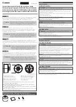
I N S T A L L A T I O N   I N S T R U C T I O N S

Large Flat Panel Swingarm Wall Mount

MSPDCCS4

Summary of Contents for MSPDCCS4

Page 1: ...I N S T A L L A T I O N I N S T R U C T I O N S Large Flat Panel Swingarm Wall Mount MSPDCCS4 ...

Page 2: ...tructions CAUTION A CAUTION alerts you to the possibility of damage or destruction of equipment if you do not follow the corresponding instructions WARNING Failure to read thoroughly understand and follow all instructions can result in serious personal injury damage to equipment or voiding of factory warranty It is the installer s responsibility to make sure all components are properly assembled a...

Page 3: ...e de boca Gabelschlüssel Chave de bocas Chiave a punte aperte Steeksleutel Clé à fourche By Hand A mano Von Hand Com a mão A mano Met de hand À la main Hammer Martillo Hammer Martelo Martello Hamer Marteau Pencil Mark Marcar con lápiz Stiftmarkierung Marcar com lápis Segno a matita Potloodmerkteken Marquage au crayon Drill Hole Perforar Bohrloch Fazer furo Praticare un foro Gat boren Percez un tro...

Page 4: ...LLATION 1 4 6 4mm 2 1 2 12 7mm 3 8 9 5mm 7 16 11 1mm 9 16 14 3mm 0 1 875x 340x 125 P 4 used with C L 5 32 D 4 A 1 N 1 E 1 F 1 G 1 D 4 H 4 J 2 K 8 L 4 M 1 Q 1 R 8 3 16 7 32 M6 x 35mm 8 32 x 3 8 10 32 x 1 1 4 5 16 18 3 8 M6 x 20mm B 1 S 4 C 4 1 4 3 8 3 8 x 2 1 2 ...

Page 5: ... Q arm assembly B and into wood supports 1 Q x4 B 3 1 x4 2 x4 S x4 9 16 14 3mm 1 4 1a Concrete Installation WARNING FAILURE TO PROVIDE ADEQUATE STRUCTURAL STRENGTH FOR THIS COMPONENT CAN RESULT IN SERIOUS PERSONAL INJURY OR DAMAGE TO EQUIPMENT It is the installer s responsibility to make sure the structure to which this component is attached can support five times the combined weight of all equipm...

Page 6: ...LATES 1 Orient faceplate A as shown in figure at left 2 Align mounting holes in faceplate A with mounting holes in back of display 3 Secure faceplate A to display using four M6 x 20mm Phillips pan head screws H NOTE The threaded inserts in the mounting holes of some displays may require the use longer mounting hardware For these instances use the two M6 x 35mm J Phillips pan heads screws provided ...

Page 7: ...ceplate A with tabs on upper portion of arm assembly B Lower display into place pivoting threaded stud on faceplate A into slot on arm assembly B 2 Install spacer O washer N and nut M onto threaded stud and tighten securely 4 CABLE MANAGEMENT CAUTION Ensure that adequate cable slack exists for movement of display and that cables will not be pinched by installation of covers D or screws K 1 Careful...

Page 8: ...5 to 15 3 Tighten pitch adjustment knob 6 1 Extension and Swivel WARNING Excessive loosening or tightening of adjustment screws can result in serious personal injury or damage to equipment 1 Using appropriate hex key loosen or tighten adjustment screws as required to achieve desired tension 15 0 15 2 3 9 16 14 3mm 1 1 ...

Page 9: ...Installation Instructions MSPDCCS4 9 ...

Page 10: ... 952 894 6918 Europe A Fellenoord 130 5611 ZB EINDHOVEN The Netherlands P 31 40 2668620 F 31 0 40 2668615 Asia Pacific A Room 30I Block D Lily YinDu International Building LuoGang BuJi Town Shenzhen CHINA Post Code 518112 P 86 755 8996 9226 8996 9236 8996 9220 F 86 755 8996 9217 8805 000227 2007 Chief Manufacturing www chiefmfg com 02 07 ...

Reviews: