I N S T A L L A T I O N I N S T R U C T I O N S
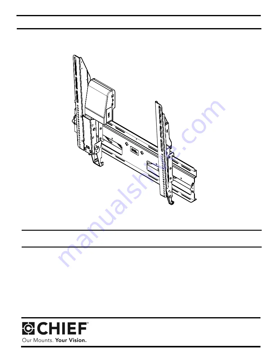
Automated Tilt Mounting System
CM8
Page 1: ...I N S T A L L A T I O N I N S T R U C T I O N S Automated Tilt Mounting System CM8 ...
Page 2: ... from outlet before putting on or taking off parts Use this mounting system only for its intended use as described in these instructions Do NOT use attachments not recommended by the manufacturer Never operate this mounting system if it has a damaged cord or plug If it is not working properly return the mounting system to a service center for examination and repair Keep the cord away from heated s...
Page 3: ... fourche Aç k Uçlu Anahtar Villáskulcs By Hand A mano Med hånden Von Hand För hand Com a mão Käsin A mano cznie Met de hand À la main El le Kézzel Hammer Martillo Hammer Hammer Hammare Martelo Vasara Martello otek Hamer Marteau Çekiç Kalapács Pencil Mark Marcar con lápiz Blyantmærke Stiftmarkierung Pennmarkering Marcar com lápis Piirretty merkki Segno a matita Oznaczenie o ówkiem Potloodmerkteken ...
Page 4: ...m G4 6 M5x16mm G5 6 M5x20mm G6 6 M5x25mm G7 6 M6x16mm G8 6 M6x25mm G10 6 M8x20mm G11 6 M8x30mm G12 4 M8x50mm G9 1 M5 G13 8 750x 323x 250 G14 8 750x 344x 500 H1 4 5 16 H2 4 5 16 x 2 1 2 H3 2 10 24 x 1 2 H4 4 J 1 C1 1 Wall Bracket Non Motorized Mounting Bracket Pin Motorized Mounting Bracket Optical Cable IR Receiver Remote Control Universal Washer Anchor E 1 Listed Power Supply ...
Page 5: ...Installation Instructions 5 DIMENSIONS ...
Page 6: ...n for further information Wood Stud Installation NOTE Mount the wall bracket to at least two 2 x 4 wood studs spaced a minimum of 12 30 4 cm to a maximum of 24 61 0 cm apart The wood studs may be covered with wall board having a maximum thickness of 1 2 1 Using a stud finder locate and mark the two studs to which the CM8 will be installed 2 Using a nail through the center hole of the wall bracket ...
Page 7: ...es 2 Drill four 1 2 x 2 1 2 12 5mm x 63 5mm pilot holes into mounting surface 3 Install four anchors H4 into pilot holes inserting end that opens slightly first Tap with hammer until flush with concrete surface 4 Using a socket wrench install four 5 16 x 2 1 2 hex head lag screws H2 and four 5 16 flat washers H1 5 Slide latches to outside 1 x 4 H2 x 4 H1 x 4 5 5 1 2 x 2 1 2 12 5mm x 63 5mm 4 3 H4 ...
Page 8: ... with upper and lower mounting holes on left side of display NOTE For mounting pattern widths less than 10 1 4 reverse location of brackets A and C 5 Adjust mounting bracket C position until mark made in Step 1 aligns with center mark in bracket C NOTE Vertical center of mounting bracket is at bottom of third slot 6 Secure bracket C to display using the screws provided G1 through G8 and G10 throug...
Page 9: ...ways use two people and proper lifting techniques when installing or positioning display on wall bracket 1 Slide wall bracket B side latches out 2 Place display on wall bracket B by hooking the mounting bracket hooks over the top of the wall bracket 3 Secure display by sliding side latches in 4 Optional For additional security install two 10 24 x 1 2 Phillips head self tapping screws H3 and or pad...
Page 10: ...ts whether the display is ON or OFF by detecting whether the LED light red from the Digital Optical Audio Output is ON or OFF In Auto Mode the CM8 tilts the display down when the LED light is ON and returns the display to the upright position when the LED light is OFF NOTE Use an optical splitter not provided to send signals to the control box if the Digital Optical Audio Output of the display is ...
Page 11: ...emote control J to fully tilt down the display NOTE The CM8 is designed to tilt the display down a maximum of 13 The maximum tilt angle may vary depending on the application 2 Visually check to see if the display tilts down fully If the display does NOT tilt down fully proceed to Section 6 If the display DOES tilt down fully proceed to Section 7 Tilt Down 1 13 ...
Page 12: ...Phillips screw from latch 3 Lower latch to remove spring 4 Return latch to original position 5 Store spring in plastic cover 6 Reinsert screw holding the latch 7 Reinstall plastic cover using two screws removed in Step 1 8 Use the down arrow button on the remote control J to tilt down the display The display should now tilt down fully Spring 1 2 x 2 x 1 3 4 5 7 6 x 1 x 2 ...
Page 13: ...Installation Instructions 13 7 Adjusting Upright Position of Display Optional 1 Adjust upright position of display 2 by turning the bottom screw on the motorized bracket A 1 A ...
Page 14: ...ng dependent on tilt angle desired Insert pin into P1 for maximum preset tilt angle of approximately 6 Insert pin into P2 for maximum preset tilt angle of approximately 9 Insert pin into STORE for full tilt angle of 13 Insert pin into UP to lock the display in the up position approximately 5 STORE P2 P1 UP P1 UP P2 STORE 1 C1 ...
Page 15: ...MC Safety A sample of the product has been tested by Bontek Compliance Testing Laboratories Underwriters Laboratories Test report reference BCT08KR 881E 08CA16246 Applied standards EN55013 2001 A1 2003 A2 2006 EN61000 6 1 2007 EN61000 3 2 2006 EN61000 3 3 1995 A1 2001 A2 2005 UL1678 UL2442 2 2007 UL60950 1 Means of conformity We declare under our sole responsibility that this product is in conform...
Page 16: ...mpany www chiefmfg com 11 09 USA International A 8401 Eagle Creek Parkway Savage MN 55378 P 800 582 6480 952 894 6280 F 877 894 6918 952 894 6918 Europe A Fellenoord 130 5611 ZB EINDHOVEN The Netherlands P 31 0 40 2668620 F 31 0 40 2668615 Asia Pacific A Office No 1 on 12 F Shatin Galleria 18 24 Shan Mei Street Fotan Shatin Hong Kong P 852 2145 4099 F 852 2145 4477 ...