background image

E N G I N E  

6 - 5 5

7.  Position tip of tool  between crankshaft and seal seat 

in cylinder case.

8.  Position  seal  between  crankshaft  and  tip  of  tool  so 

that seal  bead contacts tip of tool.

NOTE:  Make  sure  that  oil-seal  lip  is 

positioned toward  front of engine (fig.  14V).

9.  Roll  seal  around  crankshaft  using  tool  as  a 

“shoehorn”  to  protect  seal  bead  from  sharp  corner 

of seal seat surface in cylinder case.

CAUTION: 

Installation  tool  must  remain  in 

position  until  seal  is  properly  positioned  with 

both ends flush with  block.

10.  Remove tool,  being careful  not to withdraw seal.

11.  Install  seal  half in  bearing  cap,  again  using  tool  as 

a  “shoehorn”,  feeding  seal  into  cap  using  light 

pressure with thumb  and  finger.

12.  Install  bearing  cap  to  case  with  sealant  applied  to 

the  cap-to-case  interface  being  careful  to  keep 

sealant off the seal split line (fig. 15 V).

13.  Install  the  rear  main  bearing  cap  (with  new  seal) 

and torque  to specifications.

Torsional  Damper

Removal

1.  Remove  fan belt, fan  and pulley.

2.  Remove the radiator shroud  assembly as outlined in 

Section  13.

NOTE:  If  additional  operations  (such  as 

camshaft  removal)  are  not  being  performed, 

the radiator removal will not  be necessary.

3.  Remove  accessory drive pulley then  remove  damper 

retaining bolt.

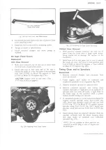
4.  Install  Tool  J-23523  on  damper  then,  turning  puller 

screw, remove damper (fig.  16V).

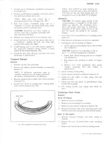
DUST  SEAL

OIL  SEAL

Fig.  14V—Crankshaft  Oil  Seal  (Rear  Main)

NOTE:  Tool  J-23523  has  holes  forming  two 

patterns.  A  two  bolt  and  a  three  bolt  pattern.

The  holes  for  the  two  bolt  pattern  must  be 

elongated  for use on the Mark IV V8  engines.

Installation

CAUTION: 

The  inertial  weight  section  of  the 

torsional damper is assembled to the hub  with a 

rubber  type  material.  The  installation  proce­

dures  (with  proper  tool)  must  be  followed  or 

movement  of the  inertia  weight  section  on  the 

hub  will  destroy  the  tuning  of  the  torsional 

damper.

1.  Coat  front cover seal contact  area (on damper) with 

engine oil.

2.  Place damper in position over key on crankshaft.

3.  Pull damper onto crankshaft as follows:

a.  Install appropriate threaded end of Tool J-23523 

into crankshaft.

CAUTION: 

Install tool in  crankshaft so  that  at 

least  1/2"  of thread engagement is obtained.

b.  Install  plate,  thrust  bearing  and  nut  to  complete 

tool installation.

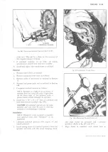
c.  Pull  damper  into  position  as  shown  in  Figure

17 

V.

d.  Remove  tool  from  crankshaft  then  install 

damper  retaining  bolt  and  torque  to 

specifications.

4.  Install accessory drive pulley.

5.  Install radiator shroud  as outlined  in Section  13.

6.  Install  fan  and  pulley  to  water  pump  hub  and 

tighten securely.

7.  Install  fan  belt  and  adjust  to  specifications  using 

strand  tension gauge.

8.  Fill  cooling  system,  start  engine  and  check  for 

leaks.

Crankcase  Front  Cover 

Removal

Small  V8  Engine

1.  Remove oil pan  as outlined.

2.  Remove  torsional damper as outlined.

3.  Remove water pump as outlined  in Section 6K.

4.  Remove  crankcase  front cover  attaching  screws  and 

remove front cover and gasket,  then discard gasket.

M ark  IV   V8  Engine

1.  Remove  torsional  damper  and  water  pump  as 

outlined.

2.  Remove  the  two,  oil  pan-to-front  cover  attaching 

screws.

3.  Remove the  front cover-to-block attaching screws.

LIGHT  DUTY  TRUCK  SERVICE  MANUAL

Summary of Contents for Light Duty Truck 1973

Page 1: ......

Page 2: ...one major subject is a Table of Contents which gives the page number on which each major subject begins An Index is placed at the beginning of each major subject within the section Summaries of Specia...

Page 3: ...e of specific service methods that can damage the vehicle or render it unsafe are stated in this service manual It is also important to understand these warnings are not exhaustive We could not possib...

Page 4: ......

Page 5: ...KES LIGHT DUTY 6 ENGINE 6K ENGINE COOLING TRUCK 6M FUEL SYSTEM SERIES 10 30 6T EMISSION CONTROL SYSTEMS SERVICE 6Y ENGINE ELECTRICAL 7 CLUTCH AND TRANSMISSION MANUAL 8 FUEL TANK AND EXHAUST SYSTEM 9 S...

Page 6: ......

Page 7: ...al Cab Suburban G Light Duty Forward Control K Four Wheel Drive P Forward Control First Number GVW Range J_ 4500 7150 lbs 2 5500 8200 lbs 3 6200 14000 lbs Second and Third Numbers Cab To Axle Dimensio...

Page 8: ...MUM CAPABILITY GROSS VEHICLE WEIGHT FOR THIS VEHICLE MAXIMUM FRONT END WEIGHT AT GROUND MAXIMUM REAR END WEIGHT AT GROUNO VEHICLE IDENTIFICATION NO v Fig 1 Vehicle Identification Number and Rating Pla...

Page 9: ...reated carefully when using jumper cables Follow exactly the procedure outlined below being careful not to cause sparks 1 Set parking brake and place automatic transmission in PARK neutral for manual...

Page 10: ...columns are the minimum recommended tires to qualify the vehicle for each GVW rating should not exceed 35 MPH for distances up to 50 miles If truck is towed on its front wheels the steering wheel sho...

Page 11: ...lbs 3500 lbs TOTAL WEIGHT AT GROUND 6000 lbs In trailer hauling applications the vehicle rear end weight at the ground with trailer attached must not exceed the Maximum Rear End Weight at Ground rati...

Page 12: ...3500 b 3500 5700 b 5200 G50 5200 8200 9 50 16 5D 30 9 50 16 5D 60 3800 b 3800 F60 3800 5700 b 5700 G51 5560 C20903 E62 or E63 Pickups 6400 8 57 16 5C b 40 8 57 16 5C b 45 3800 b 3500 b 3500 5700 b 400...

Page 13: ...t05 7500 G60 7000 LS9 or LF8 C31003 Cab Chassis with dual rear wheels 135 5 8000 7 00 16C b 45 7 00 16C b 40 3800 b 3500 b 3500 7500 R05 5700 b 5700 9000 7 00 16C b 45 7 00 16C b 45 3800 b 3800 F60 36...

Page 14: ...00 b 3582 AT 5 F58 7150 L78 15D 32 L78 15D 36 3400 b 3700 b 3400 3750 b 4500 b 3750 F58 AT5 6800 8 75 16 5C b 40 8 75 16 5C b 45 3500 b 3700 b 3500 5700 b 5600 b 3980 or 7 50 16C 40 or 7 50 16C 45 350...

Page 15: ...7 50 16D 60 60 4000 b 4000 b 4400 b 4400 b 3980 4000 7500 b 7500 b 6200 b 6200 b 4700 4880 8200 9 50 16 5D or 7 50 16C 35 45 9 50 16 5D or 7 50 16E 60 75 4000 b 4000 b 4400 b 4400 b 4000 4000 7500 b...

Page 16: ...6 5D or 7 50 16C 60 45 4300 b 4300 b 4400 b 4400 b 4090 4120 7500 R05 7500 R05 6200 b 6200 b 6200 6200 10500 7 50 16D 45 7 50 16C 45 4300 b 4400 b 4300 7500 R05 6200 b 6200 11300 7 50 16D 50 7 50 16C...

Page 17: ...3900 b 3900 F60 3900 5700 b 5500 G50 5360 LS9 F59 LOAD CAPACITY CHART MINIM UM M A N D A T O R Y E Q U IP M EN T F O R GVW R A T IN G 1973 M O D E L S W H E E L BASE GROSS V E H I C L E W EIG H T R A...

Page 18: ...engine oils will be better quality and perform better than those identified with SA through SD designations and are recommended for all light duty gasoline trucks regardless of model year and previou...

Page 19: ...ck oil should be added as necessary The oil level should be maintained in the safety margin neither going above the FULL line nor below ADD OIL line NOTE The oil gauge rod is also marked Use SE Engine...

Page 20: ...to bring transmission up to normal operating temperature approximately 180 190 F 2 Park vehicle on a level surface 3 Place selector lever in Park and leave engine running 4 Remove dipstick and wipe cl...

Page 21: ...should be thoroughly cleaned before repacking with lubricant Front wheels are equipped with tapered roller bearings on all trucks Wheel bearings should be lubricated every 24 000 miles Do not mix whe...

Page 22: ...movement at certain points in the cab or body Noise wear and improper operation at these points will result when a protective film of lubricant is not provided For exposed surfaces such as door check...

Page 23: ...y operated in Canada use SAE 80 GL 5 Gear Lubricant Air Vent Hoses Check vent hose at front axle and at transfer case for kinks and proper installation every 6 000 miles or 4 months Transfer Case Chec...

Page 24: ...eplace L 6 Rotate V 8 Replace V 8 at 24 000 miles 9 Distributor L 6 12 000 Miles Replace cam lubricator 10 Distributor V 8 12 000 Miles Replace cam lubricator 11 Master Cylinder 6 000 Miles Delco Supr...

Page 25: ...e No 11 or equivalent As required Check add fluid when necessary 11 Transmission Manual Automatic 6 000 Miles 6 000 Miles GL 5 Dexron or equivalent As required As required Keep even w filler plug See...

Page 26: ...red 9 Air Cleaner Element 12 000 Miles Replace L 6 Rotate V 8 Replace V 8 at 24 000 Miles 10 Distributor L 6 V 8 12 000 Miles Replace Cam Lubricator 11 Transmission Synchromesh Automatic 6 000 Miles 6...

Page 27: ...1A 7 Blower Switch 1A 9 Resistor Unit 1A 9 Diagnosis 1A 10 GENERAL DESCRIPTION Heating components are attached to the dash panel on the right side of the vehicle The blower and air inlet assembly and...

Page 28: ...K Models HEATER A DEFROSTER ASM HEATER A DEFROSTER ASM HEATER IN OFF POSITION AIR OUTLET AIR OUTLET VIEW A VIEW B STEERING COLUM N DEFROSTER DUCT ASM BLOW ER A AIR INLET ASM VIEW B AI R F L O W L E G...

Page 29: ...loor and or defroster dash outlets by the defroster door The temperature of the outlet air is dependent on the ratio of heated to unheated air controlled by the temperature door TURE door in the heate...

Page 30: ...upward actuates the three speed blower motor LOW MED HI COMPONENT PART REPLACEMENT BLOWER MOTOR Removal Fig 4 1 Disconnect battery ground cable G Models Remove the battery 2 Disconnect the blower moto...

Page 31: ...duct rearward out of the heater case retainer 6 Remove the four heater case to dash screws and HEATER AND AIR CONDITIONING 1A 5 then remove the heater case and core as an assembly Tilt the case assem...

Page 32: ...free from kinks or binding and doors should close properly If cable adjustment is necessary see Bowden Cable Adjustment LEFT DISTRIBUTOR DUCT G Models Replacement Fig 8 1 Disconnect the battery groun...

Page 33: ...ower switch wiring harness 6 Remove the control through the radio opening 7 If a new unit is being installed transfer the blower switch to the new unit 8 To reinstall reverse Steps 1 6 above G Models...

Page 34: ...rews 5 Pry off the cable eyelet clip at both the door and control lever Remove the cable attaching screw at both door and control locations 6 Attach a 4 piece of wire to the door end of the cable Plac...

Page 35: ...bove BLOWER SWITCH C K Models Replacement Fig 10 1 Disconnect the battery ground cable 2 Remove the instrument panel bezel 3 Remove the control to instrument panel screws and lower the control onto th...

Page 36: ...o m o f n o z z l e t o h e a t e r l o c a t i n g t a b A d j u s t 6 Check p o s i t i o n o f d e f r o s t e r n o z z l e o p e n i n g s r e l a t i v e t o i n s t r u me n t p a nel o p e n i...

Page 37: ...R CORE Feel temperatures of heater inlet and o utle t hoses WARM INLET AND OUTLET HOSES Check engine therm ostat LITTLE OR NO CHANGE IN AIR FLOW LOW OR NO AIR FLOW LOW AIR FLOW Check heater o utle t f...

Page 38: ...E OK 1 The follow ing tests should be made w ith the ignition switch in R U N position the blower speed switch O N and the lever on heat position I Check blower m oto r ground POOR OR NO GROUND I 1 GR...

Page 39: ...HEATER AND AIR CONDITIONING 1A 13 Fig 14 Heater Wiring Diagrams LIGHT DUTY TRUCK SERVICE MANUAL...

Page 40: ...nd fan unit mounted as shown in Figures 15 and 16 Heater hoses extend from the unit to the front of the vehicle where they are connected to the standard heater hoses with tees An on off water valve is...

Page 41: ...n as Fig 1 8 A u x ilia ry H ea te r Control Typical in the core inlet line During the summer months this valve should be placed in the off position Fan Switch Fig 18 The three speed fan switch LOW ME...

Page 42: ...procedures will not be repeated in this section CAUTION G Models When replacing heater hoses maintain a 1 1 4 minimum clearance between the auxiliary heater core lines and the exhaust pipe Observe mi...

Page 43: ...Overhead Air Conditioning check that the connectors have not been interchanged with one another MED 3 BLOWER M RESISTOR 152k 72 5 l 5 2 k 140RG 52 52I I 1791 I u n p n 4 BLK I40RG 14 LT BLU 14 YEL 0 D...

Page 44: ...3 Foreign Material in the System 1A 53 Refrigerant Line Connections 1A 53 Repair of Refrigerant Leaks 1A 54 Refrigerant Hose Failure 1A 54 Compressor 1A 55 Compressor Failure 1A 57 False Compressor Se...

Page 45: ...ed temperature During heating only operations the evaporator will not be in operation and ambient air will be warmed to the desired level in the same manner The dash outlets are rectangular in design...

Page 46: ...hen we hold our hands out toward the fireplace heat flows from the hot fire out to our cold hands fig 23 When we make a snowball heat always flows from our warm hands to the colder snow In an icebox t...

Page 47: ...soon got quite warm and in a couple of hours the butter in the icebox would begin to melt the milk would start to sour and the vegetables would wilt The drain water was only a few degrees warmer than...

Page 48: ...arm enough to account for all the heat the ice had absorbed The only possible answer is that the latent heat had been used up to change the ice from a solid into a liquid Many substances can be either...

Page 49: ...and replaced them with two flourine atoms This newly formed fluid carried the technical chemical name of dichlorodifluoromethane Today it is sold commer cially by manufacturers as Refrigerant 12 or R...

Page 50: ...the temperature because temperature is merely a measure ment of heat intensity fig 32 Pressure in Refrigeration Because we must use pressures and gauges in air conditioning service the following poin...

Page 51: ...of the refrigerant also drops lower and lower as the liquid goes down By means of a simple system of mechanical linkage the downward movement of the float opens a valve to let refrigerant in The incom...

Page 52: ...owly consequently less heat is carried away from our body From the standpoint of comfort air conditioning should control the relative humidity of the air as well as its temperature By reducing the hum...

Page 53: ...HEATER AND AIR CONDITIONING 1A 27 LIGHT DUTY TRUCK SERVICE MANUAL...

Page 54: ...he heat into the surrounding air Now let s look at the compressor in detail and some of the components that work with these main units to complete the air conditioning system Compressor The prime purp...

Page 55: ...26 Wobble Plate and Mainshaft Assembly 40 Shaft Nut 14 Coil Housing Retainer Ring 27 Thrust Race Fig 34 Six Cylinder Compressor Cross Sectional View located in an internal groove in the neck of the f...

Page 56: ...tacts the wobble plate and one concave surface into which the drive ball fits Ten seats are provided in 0005 inch thickness variations including a basic ZERO seat for simple field gauging operations S...

Page 57: ...lf 53 High Pressure Relief 41 Oil Inlet Tube 0 Valve and 0 Ring Ring 54 Rear Head to Shell 42 Oil Inlet Tube Retaining Nuts 43 Mainshaft Rear 55 Compressor to Bearing Connector 0 Ring Fig 3 5 Six Cyli...

Page 58: ...meter hose between the compressor and condenser is the high pressure vapor discharge line These hoses are constructed with a synthetic material core covered with a woven metal mesh which is in turn co...

Page 59: ...simple It is a matter of controlling opposing forces produced by a spring and the refrigerant pressures For example The pressure in the power element is trying to push the seat away from the orifice w...

Page 60: ...o maintain proper temperatures The compressor is started and stopped through the use of an electro magnetic clutch and a thermostat affected by variations in temperature The thermostatic switch incorp...

Page 61: ...one undesirable element added or allowed to enter the system can start a chain of chemical reactions which upsets stability and interferes with the operation of the unit Chemical Instability and Refri...

Page 62: ...e doubles the chemical action While temperature alone can cause the synthetic rubber parts to become brittle and possibly to decompose the increased pressure can cause them to rupture or blow As the t...

Page 63: ...with some other refrigerants the eventual formation is as damaging If the operating pressure and temperature in the evaporator is reduced to the freezing point moisture in the refrigerant can collect...

Page 64: ...nd the temperature lever is at full COLD the air inlet door is positioned to reduce the supply of outside air to the system from 100 to approximately 20 The remainder of the air input 80 to the A C sy...

Page 65: ...r motor Temp Knob This knob is used to control the degree of cooling desired Fully clockwise at CITY provides maximum cooling while turning the knob to HIWAY provides adequate cooling for highway oper...

Page 66: ...frigeration capacity of the entire system can be greatly reduced by a single kink The flexible hose lines should never be bent to a radius of less than 10 times the diameter of the hose The flexible h...

Page 67: ...conditioning dealer can use the equipment on hand and avoid duplication The J 8393 Charging Station is a portable assembly of a vacuum pump refrigerant supply gauges valves and most important a five 5...

Page 68: ...before operating Keep all openings capped when not in use to avoid moisture being drawn into the system Oil should be changed after every 250 hours of normal operation To change oil simply unscrew he...

Page 69: ...tch for color changes The color of the flame which passes through the reaction plate will change to green or yellow green when sampling hose draws in very small leaks of R 12 Large leaks will be indic...

Page 70: ...nt a low refrigerant level will cause a dangerous lack of lubrication Therefore the refrigerant charge in the system has a definite tie in with the amount of oil found in the compressor and an insuffi...

Page 71: ...t part can be safety removed 1 With the engine stopped install high and low pressure lines of Charging Station gauge set to the proper high and low pressure gauge fittings See Installing The Charging...

Page 72: ...oil in container Open valve on oil adding tool until oil level in container is reduced by an amount equal to that lost during discharge of system plus 1 2 ounce then close valve Take care not to add...

Page 73: ...removing gauge lines from fittings be sure to remove the adaptersfrom the fittings rather than the gauge lines from the adapters PERFORMANCE TEST Under normal circumstances it will not be necessary to...

Page 74: ...0 240 270 290 Accumulator 20 20 21 22 23 Pressure 26 28 29 30 32 Discharge Air Temp at Right Hand Outlet 41 47 41 47 42 50 43 51 43 51 Overhead System G Models Refrigerant Charge 5 lbs 4 oz Temperatur...

Page 75: ...ssor as follows a If the quantity drained was 4 fluid oz or more add the same amount of new refrigeration oil to the replacement compressor b If the quantity drained was less than 4 fluid oz add 6 flu...

Page 76: ...eck with leak detector Correct leak if any and fill system to proper charge No bubbles Sight glass clear System is either fully charged or empty Feel high and low pressure pipes at compressor High pre...

Page 77: ...stripped or otherwise damaged threads C K Models 1 Install the gauge set and set up the vehicle as described under Performance Test 2 Set the control at A C HI blower max COLD and run the engine at 2...

Page 78: ...stalled power element bulb Attachment of the expansion valve bulb to the evaporator outlet pipe is very critical The bulb must be attached tightly to the pipe and must make good contact with the pipe...

Page 79: ...ngine in closed or improperly ventilated garages FOREIGN MATERIAL IN THE SYSTEM Whenever foreign material is found in the system it must be removed before restoring the system to operation In the case...

Page 80: ...damaged in any way Coat the new O ring with clean refrigeration oil and install carefully 4 Retorque the fitting using a backing wrench 5 Evacuate charge and check the system Leaks at Hose Clamp Conne...

Page 81: ...Home Chassis Models Removal Fig 56 1 Disconnect battery ground cable 2 Disconnect compressor clutch connector 3 Purge the system of refrigerant 4 Release the belt tension at the idler pulley and remo...

Page 82: ...On some G and Motor Home Chassis models it may be necessary to increase idler pulley slack adjustment This may be accomplished by 1 Remove and discard the idler adjustment bolt 2 Remove the idler bac...

Page 83: ...the system has been exposed to the atmosphere will determine the replacement of parts and processing that will be required The greater the length of time of exposure to the atmosphere the greater wil...

Page 84: ...ort 5 Remove the left grille support to upper fender support 2 screws 6 Disconnect the condenser inlet and outlet lines and the outlet tube line at the right end of the condenser Cap or plug all open...

Page 85: ...Steps 1 5 above replace sealer as necessary EVAPORATOR CORE Replacement Fig 59 1 Disconnect the battery ground cable 2 Purge the system of refrigerant 3 Remove the nuts from the selector duct studs pr...

Page 86: ...mounting strap screws and remove the core 11 To install reverse Steps 1 10 above 12 Refill coolant system and connect the battery ground strap KICK PAD VALVE Replacement Fig 63 1 Disconnect the vacuum...

Page 87: ...switch assembly 5 To install a new switch reverse Steps 1 4 above VACUUM TANK The vacuum tank is mounted to the engine side of the dash panel above the blower assembly fig 65 Replacement 1 Disconnect...

Page 88: ...sconnect the wiring harness at the switch 3 Remove the switch to case screws and remove the switch carefully so as not to damage the capillary tube NOTE Note capillary tube position in the core so tha...

Page 89: ...tion oil when installing the switch 6 Evacuate charge and check system operation FUSE A 25 amp fuse located in the junction block protects the entire air conditioning system except for the blower when...

Page 90: ...ion REAR DUCT This duct covers the blower evaporator assembly at the rear of the vehicle and incorporates four adjustable air outlets fig 70 Replacement 1 Disconnect the battery ground cable 2 Disconn...

Page 91: ...emove the lower to upper blower evaporator case screws and lower the lower case and motor assembly CAUTION Before removing the case screws support the lower case to prevent damage to the case or motor...

Page 92: ...coated with clean refrigeration oil 2 Install the sensing bulb making sure that the bulb makes good contact with the core outlet line 3 Install the lower case and blower motor assemblies Connect the...

Page 93: ...le 2 Remove the switch retaining screws 3 Disconnect the wiring harness at the switch and remove the switch 4 To install reverse Steps 1 3 above FUSE The Four Season portion of this system is protecte...

Page 94: ...ystem AIR DISTRIBUTOR DUCT ASSEMBLY Replacement Fig 78 1 Remove four screws that hold the duct to the engine cover 2 Lift upward and rearward on the top of the distributor duct assembly and move it aw...

Page 95: ...ining screws and remove core 5 Remove blower motor and harness assembly from case 6 To install reverse Steps 1 5 above NOTE Add 3 fluid ounces of new refrigera Fig 79 Blower Evaporator G Floor Mounted...

Page 96: ...nd cable and compres sor clutch connector 2 Remove the blower evaporator cover as described previously 3 Disconnect the electrical harness at the switch 4 Remove the attaching screws and remove the sw...

Page 97: ...83 3 Remove superheat switch from the rear head by Fig 82 Superheat Switch Schematic Fig 83 Superheat Switch Removal pulling at the terminal housing groove with J 9393 or a pair of screwdrivers 4 Rem...

Page 98: ...momentary switch contact closings during certain transient conditions A blown thermal fuse indicates that the air conditioning system is either low or completely out of refrigerant charge a malfuncti...

Page 99: ...tem Fig 88 Blower Motors G Overhead System motor and wheels Remove the wheels from the motor shaft Installation 1 Place the blower wheels onto the motor shaft and install the setscrews do not tighten...

Page 100: ...ssembly Cap or plug all open connections at once 6 Remove the blower evaporator to roof panel attachments and lower the blower evaporator assembly Remove the assembly and place on a work bench upside...

Page 101: ...the blower evaporator assembly Remove the assembly and place it on a work bench upside down 7 Remove the lower to upper case screws and remove the lower case assembly Remove the upper shroud and uppe...

Page 102: ...nd cable 2 Purge the system of refrigerant 3 Disconnect the inlet and outlet lines at the receiver dehydrator and cap or plug the open lines at once 4 Remove the receiver dehydrator bracket attaching...

Page 103: ...panel side of the unit when the motor is placed in the case as illustrated in Figure 96 Do not tighten setscrews at this point 2 Place the motor in the bracket with the electrical connector side of t...

Page 104: ...in one of four ways Noise seizure leakage or low discharge pressure fig 99 NOTE Resonant compressor noises are not cause for alarm however irregular noise or rattles may indicate broken parts or exces...

Page 105: ...e check to determine if the evaporator pressure can be obtained 3 The system will also indicate a low refrigerant charge by bubbles occurring in the sight glass Evaporator When the evaporator is defec...

Page 106: ...itch is defective replace ________ Check for proper ground and good clean electrical contact at terminals Check fo r proper air gap Correct if necessary 022 057 Check and correct belt tension R EFR IG...

Page 107: ...m Check Inlet Outlet Pipe Temperatures Not Engaged Apply External Ground to Compressor if Clutch is Still not Engaged Replace Compresor Clutch See the Overaul Manual j System O K Engaged Check For Blo...

Page 108: ...ATELY AFTER RESTART AND PULL DOWN OF EVAPORATOR PRESSURE NORMAL EVAPORATOR PRESSURE LOW EVAPORATOR PRESSURE CHECK EVAPORATOR PRESSURE CHECK EVAPORATOR OUTLET LINE EVAPORATOR OUTLET LINE WARM I HIGH EV...

Page 109: ...M P L IG H T S L LA M P DOES N O T L IG H T I With ignition switch in R u n position and heater or A C on use 12 volt test lamp to check for voltage at resistor connector w ith blower speed switch in...

Page 110: ...e pressure switch to compressor clutch solenoid G M ODEL SYSTEMS 1 Wire from fuse panel to blower switch 2 Blower switch 3 Wire from blower switch to therm ostatic switch 4 Therm ostatic switch 5 Wire...

Page 111: ...al fuse Replace expansion valve according to normal procedures recharge system and then replace the thermal fuse Install new thermal fuse Jump connector plug B C terminals during charging and replace...

Page 112: ...ITCH Engine O FF l e a d disconnected from Superheat Switch terminal Continuity between switch housing and ground If not grounded check continuity switch housing to retainer ring and retainer ring to...

Page 113: ...m is now normal then the problem lies downstream b Vacuum Less Than Normal at Some Positions If vacuum was low at one or several of the selector lever positions a leak is indicated in these circuits c...

Page 114: ...LOWER MOTOR BLK THERMOSTATIC SWITCH DISCHARGE PRESSURE SWITCH O POS CIRCUIT OFF BATT ONLY MED 1 BATT M1 RES MED 2 BATT M2 RES HIGH BATT BLOWER Fig 104 Four Season System Wiring Diagram C K Models 1A 8...

Page 115: ...LIGHT DUTY TRUCK SERVICE M A N U A L HEATER AND AIR CONDITIONING 1A 89...

Page 116: ...SE FUSE PANEL I 52 I 50 I 51 72 J S _ HI BAT POS CIRCUIT OFF B A H ONLY LO BATT LO MED BATT MED HI BATT HI BLOWER SWITCH i 4 i 0 52 16 YEL1 16 ORN 10 PPL v s l CN 1 j I BLOWER MOTOR Fig 106 0verhead S...

Page 117: ...0 I C V HEATER CONTROL SWITCH CONNECTOR I P WIRING JL r l 3 I lh 31 01 p t J 6 BLOWER RELAY Is 60 H 10 ORN BLK1 16 GRN DK 18 BLK 18 ORN 10 ORN BLK 16 YEL BLK 10 BLK ORN POS CIRCUIT OFF BAH ONLY LO BAT...

Page 118: ...REAR GRD BLOWER SWITCH FRONT TIE RELAY FRONT TO REAR POS CIRCUIT OFF BAH ONLY LO BAH LO MED BAH LO MED HI BAH L M HI BLOWER MOTOR REAR BLOWER SWITCH REAR Fig I08 Floor 0verhead System Wiring Diagram G...

Page 119: ...O FUSE PANEL RESISTOR COMPRESSOR BLOWER SWITCH SET AT CONNECTION OFF N TO NONE LOW N TO I 2 MED N TO 1 A 4 HIGH N TO 1 3 4 4 THERMOSTATIC SWITCH BLOWER SWITCH Fig 109 Motor Home Chassis Wiring Diagram...

Page 120: ...9399 9 16 Thin Wall Remover 5 J 5420 Gauge Line Adapter Socket 27 J 9432 Needle Bearing Installer 6 J 6084 Leak Detector 18 J 9401 Hub and Drive Plate 28 J 9553 Seal Seat O Ring 7 J 8433 Puller Assem...

Page 121: ...IS PART CONTENTS OF THIS SECTION General Description IB 1 C K Models IB 4 G Models IB 30 Special Tools IB 48 GENERAL DESCRIPTION On the following pages service procedures will be given for components...

Page 122: ...ndow is available Utility Utility models are designated with the number 14 See figure 4 An optional removable roof is also available Vans G Series Vans are available in two model number designations S...

Page 123: ...BODY 1B 3 Fig 6 Typical 06 Van LIGHT DUTY TRUCK SERVICE MANUAL...

Page 124: ...sweep of blades turn on wipers and note sweep of arms If necessary remove one or both arms as follows Pull outer end of arm away from glass which will trip lock spring at base of arm and release spri...

Page 125: ...gained by reaching into compartment opening with door partially open Fig 10 Rear View Mirror Below Eyeline Adjustment Engagement of lock in striker may be adjusted by loosening striker retaining screw...

Page 126: ...is increased by such conditions as wind pressures extremes of temperature motion of the vehicle etc NOTE The procedure for removal of the windshield applies to other stationary glass applications such...

Page 127: ...older weld high spots or hardened spot weld sealer Remove all high spots Fjg 16_ Rem0ving Windshield from Opening 3 Check windshield glass to opening by supporting glass with six spacers contained in...

Page 128: ...Base Weatherstrip Bend the locking strip over and use a thin bladed tool to lock weatherstrip tightly against windshield See figure 18 for detail b Optional Weatherstrip Use J 2189 24 and J 2189 23 in...

Page 129: ...the body opening as nearly as possible Hinge Adjustment Door hinge bolt holes are oversized to make adjustment possible Alignment adjustments can be made by loosening the proper hinge bolts aligning d...

Page 130: ...her of two positions between full open and closed The front door check hinge assembly is replaced as a complete unit as follows See figure 22 Removal 1 Loosen front fender rear bolts 2 With special To...

Page 131: ...h goes into the metal channel 4 Brush the inside of the metal glass channel freely with ordinary engine oil This will enable the glass and filler to slide freely into the channel Push the glass with t...

Page 132: ...above procedure for installation Fig 30 Door Window and Regulator WINDOW REGULATOR FIG 30 Replacement 1 Remove ventilator assembly and door window as outlined previously 2 Remove screws attaching regu...

Page 133: ...handle 3 Remove remote control rod 4 Remove trim panel 5 Remove clip from outside handle rod to lock 6 Remove screws which retain outside handle to door panel 7 Remove handle and control rod 8 Revers...

Page 134: ...sill plate retaining screws REAR SIDE DOOR 06 AND 63 ONLY Adjustments and Hinge Replacement The procedures for hinge replacement and for hinge and striker bolt adjustment are similar to those detailed...

Page 135: ...Remove window regulator handle and remote control push button knob 2 Remove trim pad 3 Disengage three clips which retain control rods to lock assembly a Inside handle control rod b Remote control lo...

Page 136: ...engage outside handle control rod from lock assembly by removing clip as shown in figure 43 Fig 42 Remote Control Assembly 3 Remove two screws securing outside handle to door panel 4 Remove handle ass...

Page 137: ...rods and latch are shown in figures 45 and 46 The rods can be disconnected from the lock latch or handle by disengaging the retaining clips as shown The lock cylinder is removed in the same manner as...

Page 138: ...embly and insulator on the inside of the door panel remove bolts securing housing assembly to door 4 Remove housing insulator and check arm 5 To separate check arm from bracket remove holding pin conn...

Page 139: ...e underside of the body See figure 50 2 Remove hinge assemblies If the hinge pins are to be removed note the position of bushings so they may be reinstalled in the same position 3 Reverse procedure to...

Page 140: ...move side latches with control rods See figure 52 NOTE Detach wiring harness from R H latch if so equipped 13 Separate side latch from control rod by pulling control rod thru nylon guide 14 Reverse th...

Page 141: ...move the hinge to endgate bolts Fig 56 Pulling Hinge Away From Body 14 Fig 57 Grasping Torque Rod 14 Fig 58 Removing Access Cover 14 4 Pull the endgate away from the body several inches and withdraw h...

Page 142: ...rom latch 5 Refer to figure 63 for installation of latch control and blockout rod 6 Disconnect blockout rod from control assembly by detaching spring and removing two screws retaining rod to inner pan...

Page 143: ...teps for reassembly TAILGATES 03 63 and 14 Replacement Utility vehicles 14 without removable tops utilize a tailgate shown in figure 69 Chassis cab 03 and 63 models have optional pickup units which ut...

Page 144: ...ar window into the endgate and lower endgate 4 Lower the door windows 5 Slide top rearward approximately 18 to expose the bottom rear top to pickup box attaching holes 6 To prevent possible flexing of...

Page 145: ...may require a second application of cleaning fluid followed immediately by a soft brush to completely remove the spot Cleaning Fabrics with Detergent Foam Cleaners This type of cleaner is excellent fo...

Page 146: ...73 through 81 CAUTION See CAUTION on page 1 of this section regarding fasteners used on seats and seat belts Fig 73 Front Bench Seat 03 06 and 63 Fig 74 Driver s Bucket Seat 03 Fig 75 Passenger s Buc...

Page 147: ...BODY IB 27 Fig 78 Rear Bench Seat 63 Fig 79 Rear Bench Seat 06 Fig 80 Rear Folding Seat 06 Fig 81 Rear Bench Seat 14 LIGHT DUTY TRUCK SERVICE MANUAL...

Page 148: ...1B 28 BODY BODY MOUNTING The sequence of mounting attachments is shown in figures 82 through 85 LIGHT DUTY TRUCK SERVICE MANUAL...

Page 149: ...BODY 1B 29 Fig 84 Body Mounting 06 Fig 85 Body Mounting 14 LIGHT DUTY TRUCK SERVICE MANUAL...

Page 150: ...turn on wipers then note sweep of arms If necessary remove one or both arms as follows Pull outer end of arm away from glass which will trip lock spring at base of arm and release spring from undercu...

Page 151: ...TOR GRILLE Replacement 1 Remove windshield wiper blades 2 Remove screws retaining grille figure 3G 3 Remove grille and seal 4 Reverse above steps to install grille COWL SIDE VENT VALVE Replacement 1 R...

Page 152: ...figure 7G When replacing a cracked windshield glass it is very important that the cause of the glass breakage be determined and the condition corrected before a new glass is installed Otherwise it is...

Page 153: ...body around windshield opening 3 Check flange area for solder weld high spots or hardened spot weld sealer Remove all high spots 4 Check windshield glass to opening by supporting glass with six spacer...

Page 154: ...Torque to specifications 2 Place window into opening and install hinge retaining screws and window 3 Install latch to glass LATCH SWINGOUT WINDOW Replacement 1 Swing out the window 2 Remove latch to b...

Page 155: ...loosen striker bolt shim to desired position and tighten bolt securely DOOR HINGE Remove 1 Remove hinge access hole cover from door hinge pillar 2 If removing one hinge support door in such a manner t...

Page 156: ...ng an oil can or similar means squirt prepsol on the glass filler all around the glass channel or frame to soften the old seal When the seal has softened remove the glass from the channel 2 Thoroughly...

Page 157: ...y in normal position level and raise straight up and out 8 Reverse above procedure for installation Fig 17G Adjusting Ventilator Tension Fig 18G Window and Regulator WINDOW REGULATOR Replacement 1 Win...

Page 158: ...ge door catch NOTE Connecting rod can be removed at this point by disconnecting spring clip from lock 4 To install reverse removal procedure LOCK CYLINDER ASSEMBLY FIG 20G Replacement 1 Raise door win...

Page 159: ...r rear latch as outlined under Door Adjustments UPPER LEFT HINGE Removal 1 Open the door 2 Disengage spring from bolt using a spring removal tool such as a brake spring removal tool 3 Close door 4 Rem...

Page 160: ...using tool J 23457 See figure 13G installation 1 Install door striker using tool J 23457 Torque to specifications 2 Adjust striker as outlined under Door Adjustments Front Latch Striker 1 Remove stri...

Page 161: ...catch mounted on the lower front roller holds the door in the full open position The catch engages a striker installed at the rear of the lower roller channel Reposition Door Up or Down 1 Partially op...

Page 162: ...after loosening with Tool J 23457 Also loosen door wedge located below striker Fore and aft adjustment is obtained by adding or deleting washers between the bolt and body pillar The striker must enter...

Page 163: ...d between the nylon block and hinge and between roller and hinge They must be installed in pairs For example if one shim is added behind the nylon block another must be added behind the roller See fig...

Page 164: ...d install bolts Snug bolts 5 Install hinge strap and its retaining pin 6 Adjust door and torque hinge bolts to specifications DOORS REAR DOOR REMOTE CONTROL Removal 1 Remove trim panel 2 Disengage upp...

Page 165: ...dures for rear door glass and weatherstrip replacement REAR DOOR ADJUSTMENTS NOTE Door adjustments are provided by slotted holes at hinge attachment in body and door 1 Remove or loosen door strikers a...

Page 166: ...at adjuster to seat Torque bolts to specifications 2 Install seat belt Torque retaining nut to specifications CAUTION Shoulder of b o l t must bottom on weldn u t 3 Install seat onto seat riser and to...

Page 167: ...val 1 Remove bolts securing seat legs to floor 2 Remove seat assembly NOTE After removing the rear seat reinstall the bolts into the anchor nuts to seal the openings from dirt and foreign matter 3 Rem...

Page 168: ...2189 Weatherstrip Tool Set 2 J 22585 Front Door Hinge Bolt Wrench 3 J 22577 Windshield Checking Blocks 4 J 7797 Door Handle Clip Remover 5 J 23457 Door Striker Bolt Remover and Installer Fig IT Speci...

Page 169: ...leaning and protective treatment is performed Using a chisel ensure that the drain provisions in the floor pan reinforcement members are open There are drain holes in the body side panels also These h...

Page 170: ...art below Frame Repair Welding Before welding up a crack in frame a hole should be drilled at the starting point of the crack to prevent spreading Widen V groove crack to allow complete weld penetrati...

Page 171: ...LIGHT DUTY TRUCK SERVICE M A N U A L Fig 2 Frame Horizontal Checking Typical FRAME 2 3...

Page 172: ...16 7 8 16 7 8 16 7 8 PA100 9 3 8 11 7 8 13 3 8 16 10 1 4 7 1 8 10 13 3 8 15 1 2 12 10 3 4 13 3 8 43 79 114 5 8 14 16 7 8 19 1 8 16 7 8 PA208 308 9 3 8 11 7 8 12 3 4 16 13 1 2 7 1 2 10 10 15 1 8 11 5...

Page 173: ...LIGHT DUTY TRUCK SERVICE M A N U A L Fig 4 10 30 Series Truck Frame FRAME 2 5...

Page 174: ...2 6 FRAME LIGHT DUTY TRUCK SERVICE MANUAL Fig 5 Underbody Reference Points G Van...

Page 175: ...Suspension 34 Steering Knuckle and Wheel Spindle 3 5 Control Arms 3 5 Ball Joints 3 5 Coil Springs 3 5 LeafSprings 3 5 Shock Absorbers 3 5 Wheel Alignment 3 9 Front Suspension Geometry 3 9 Caster 3 9...

Page 176: ...on system consists of upper and lower control arms pivoting on steel threaded or rubber bushings on upper and lower control arm shafts The lower control arms are attached to the crossmember with U bol...

Page 177: ...LIGHT DUTY TRUCK SERVICE MANUAL G 10 20 C 10 P 10 30 Fig 2 Front Suspension C P K Typical FRONT SUSPENSION 3 3...

Page 178: ...ular axle attached to the vehicle through the leaf springs that are secured to the axle on a spring pad The spring ends called eyes are attached to the vehicle frame through hangers OPERATION The stee...

Page 179: ...hock absorbers are used with the springs and are covered elsewhere in this section CONTROL ARMS Independent Suspension The front control arms are said to be the SLA type Short and Long Arm The control...

Page 180: ...r A This is accomplished by fluid moving through the outer piston holes and unseating the piston intake valve Since all the fluid in chamber B cannot pass into chamber A due to the volume of the pisto...

Page 181: ...y means of intersecting holes one along the axis of the piston rod and the other perpendicular to it As the shock absorber approaches the end of the rebound stroke the passage in the piston rod enters...

Page 182: ...ng loaded blow off valve opens as soon as the pressure is great enough to unseat the valve after which the low speed orifice ceases to have an appreciable effect As the pressure of the fluid against t...

Page 183: ...spension geometry The various factors that enter into front end geometry are covered here each one under its own heading CASTER Caster is the tilting of the front steering axis either forward or backw...

Page 184: ...aring it with the same measurement on the other arm The angle of the steering arms must be the same for both arms Toe out on turns is not adjustable STEERING AXIS INCLINATION S A I FIG 17 Steering axi...

Page 185: ...FRONT SUSPENSION 3 11 Fig 16 Toe out on Turns LIGHT DUTY TRUCK SERVICE MANUAL...

Page 186: ...ise 3 If bearings are noisy or excessively loose they should be cleaned and inspected prior to adjustment NOTE To check for loose bearings grip the tire at the top and bottom and move the wheel assemb...

Page 187: ...E A normal shim pack will leave at least two 2 threads of the bolt exposed beyond the nut If two 2 threads cannot be obtained Check for damaged control arms and related parts Difference between front...

Page 188: ...the vehicle may be in a damaged condition DEFINITIONS Service Checking Values within these limits should provide a high level of customer satisfaction and should not require resetting Service Reset V...

Page 189: ...D CASTER ANGLE l 3 4 CASTER ANGLE READING 2 4 ACTUAL CORRECTED CASTER ANGLE 1 HORIZONTAL FRAME ANGLE FRAME ANGLE 114 UP R ANGLE READING 2 ACTUAL CORRECTED CASTER ANGLE 3 V 4 0 ACTUAL CORRECTED CASTER...

Page 190: ...thdraw cotter pin 2 Remove the brake caliper and hang by wire to the suspension CAUTION Do not allow the caliper assembly to hang by the brakeflex line 3 Remove hub and disc assembly 4 Remove outer be...

Page 191: ...with soft hammer 3 Position hub and disc on spindle and install outer bearing pressing it firmly into position in hub Install hub washer and finger tighten nut 4 Install brake caliper see section 5 5...

Page 192: ...the stabilizer bar attachments to the lower control arm Fig 26A Stabilizer Bar C P and G Typical Fig 26B Stabilizer Bar K Typical Fig 27 Removing Coil Spring with Tool J 23028 3 Bolt Tool J 23028 to...

Page 193: ...pring to expand 3 Wire brush clean and inspect for broken leaves 4 Replace leaf or liners Installation CAUTION See CA UTION note on page one of this section regarding the fasteners referred to in step...

Page 194: ...amber shim in their appropriate places 5 Torque the cross shaft to frame nuts 6 Remove the safety chain and install the tire 7 Lower vehicle to the floor LOWER CONTROL ARM INNER PIVOT SHAFT AND OR BUS...

Page 195: ...rom upper control arm ball stud and loosen stud nut one turn 3 Loosen upper control arm ball stud in steering knuckle using Tool J 23742 position as shown in Figure 34 Remove the nut from the ball stu...

Page 196: ...must be at least 24 inches NOTE Always tighten the thinner shim packs nut first for improved shaft to frame clamping force and torque retention 2 Insert ball joint stud into steering knuckle and insta...

Page 197: ...ng seats firmly Fig 33C Lower Control Arm Rubber Bushing Installation CAUTION Be sure spacer J 24435 6 i s i n position as shown i n figure 33C t o avoid collapsingcontrolarm duringassembly 3 Install...

Page 198: ...que to align cotter pin not to exceed 90 ft lbs Never back off to align cotter pin B 20 30 Series 80 100 ft lbs plus additional torque to align cotter pin not to exceed 130 ft lbs Never back off1to al...

Page 199: ...ove tools and the ball joint Installation Fig 38 CAUTION See CAUTION on page 1 of t h i s section regarding the fasteners referred t o i n steps4 5 and 7 1 Start the new ball joint into the control ar...

Page 200: ...dure and tighten splash shield mounting bolt Tighten two caliper assembly mounting bolts tO 35 ft lb torque 4 Adjust wheel bearings as outlined under Front Wheel Bearing Adjustment 5 Tighten wheel nut...

Page 201: ...t wheel alignment caster e Check and align front suspension f Broken springs f Replace springs g Malfunctioning shock absorber g Diagnose shock absorbers h Broken stabilizer bar or missing link h Repl...

Page 202: ...e c Replace tire d Improper shock absorber action d Replace shock absorber EXCESSIVE OR U N EVEN T IR E W EAR a Underinflated or overinflated tires a Inflate tire to proper recommended pressure b Impr...

Page 203: ...ent d Adjust gear as outlined in Section 9 of shop manual e Power steering gear valve spool binding e See Section 9 in shop manual f Obstruction within power steering gear f See Section 9 in shop manu...

Page 204: ...3 30 FRONT SUSPENSION B A LL JO IN T D IA G N O S T IC PRO CEDURE Fig 43 Ball Joint Diagnostic Procedure except K Series LIGHT DUTY TRUCK SERVICE MANUAL...

Page 205: ...can usually be done by lifting up and pushing down on the end of the bumper near each corner of the vehicle until maximum movement up and down is reached Then let go of bumper and observe if the up an...

Page 206: ...ing noise on fast reverse a skip or lag at reversal near mid stroke IMPORTANT When air adjustable shocks are being manually operated the air line must be disconnected at the shock absorber BENCH CHECK...

Page 207: ...ced the remainder of the bench check is the same as given in the Spiral Groove Reservoir Section 1 Bench Check Procedure AIR ADJUSTABLE SHOCKS This type of shock contains an air chamber like the spira...

Page 208: ...speeds Test for Wheel Bearing Noise 1 Drive car at low speed on a smooth road 2 Turn car to develop left and right motions traffic permitting 3 Noise should change due to cornering loads 4 Jack up whe...

Page 209: ...REPLACE BEARINGS CHECK SEALS AND CHECK FOR PROPER LUBRICATION i s ii J J i S j BENT CAGE CAGE DAMAGE DUE TO IMPROPER HANDLING OR TOOL USAGE REPLACE BEARING All nmm IND ENTATIONS SURFACE DEPRESSIONS O...

Page 210: ...USED BY INCORRECT LUBRICANT OR MOISTURE RE USE BEARINGS IF STAINS CAN BE REMOVED BY LIGHT POLISHING OR IF NO EVIDENCE OF OVER HEATING IS OBSERVED CHECK SEALS AND RELATED PARTS FOR DAMAGE BRINELLING SU...

Page 211: ...ace Installer Bearing Race Installer Bearing Race Installer Bushing Replacement C 10 G 10 20 6 7 8 9 10 11 J 8092 J 9519 9 J 9519 7 J 9519 10 J 23028 01 J 23742 1 Driver Handle Ball Joint Installer Ba...

Page 212: ...ardless of the turning angle Provisions for Power Take off have been incorporated in the transfer case FRONT AXLE The front axle is a hypoid gear axle unit equipped with steering knuckles Axle assembl...

Page 213: ...e rod to allow independent movement of each steering knuckle 3 At top of knuckle apply torque wrench to one of the steering arms attaching stud nuts then check torque necessary to turn the steering kn...

Page 214: ...ng assembly Inspection 1 Wash all parts in solvent and air dry 2 Inspect all parts for wear cracks or broken teeth 3 Replace all O rings during assembly Assembly Place new 0 ring seal on actuator knob...

Page 215: ...air dry 3 Inspect all parts for wear cracks for broken teeth and replace as necessary 4 Replace all seals gaskets and O rings Installation 1 Install internal clutch gear collar and gear 2 Install loc...

Page 216: ...WASHER ACTUATING CAM BODY INTERNAL SNAP RING BUSHING HUB RING RETAINING KNOB RETAINING PLATE BOLTS AXLE SHAFT SNAP RING GEAR HUB HOUSING INNER CLUTCH GEAR ACTUATING CAM PIN INNER GASKET METAL ACTUATIN...

Page 217: ...U bolts attaching axle to front springs 4 Attach shock absorbers to axle brackets 5 Connect brake hoses to frame fittings bleed the brake system see Section 5 6 Attach connecting rod to steering arm 7...

Page 218: ...will not be damaged by the vise jaws b Remove the oil seal c Remove the needle roller bearing 8 Remove the axle shaft and joint assembly Repair The Axle Joint Components a Remove the lock rings after...

Page 219: ...ION If i t i s necessary t o remove the steeringarm discardthethreeselflocking nuts F i g 61 and replace with new nuts a t assembly 11 Remove the cotter pin from the upper ball socket nut 12 Remove th...

Page 220: ...duringknuckleremoval NOTE Remove the lower ball joint snap ring before beginning NOTE Lower ball joint must be removed Fig 6 5 In stalling Lower Ball Joint before any service can be performed on the u...

Page 221: ...mbly of the knuckle to the yoke 1 Assemble knuckle to yoke Assemble bottom torque prevailing nut Torque nut to 70 90 ft lbs NOTE If the stud turns while attempting to torque this nut assemble the top...

Page 222: ...8092 b Assemble the inner wheel bearing cup into the wheel hub using Installer J 23448 and Driver Handle J 8092 c Pack the wheel bearing cone with a high melting point type wheel bearing grease and in...

Page 223: ...ring Installer 7 J 23447 Adjusting Sleeve Spanner 3 J 8092 Driver Handle 8 J 23448 Cup and Seal Installer 4 J 9519 C Clamp 9 J 23454 1 Ball Joint Remover Installer 5 J 23445 Bearing Installer 10 J 234...

Page 224: ......

Page 225: ...ear Suspension Propeller Shaft Rear Axle 4 16 4 8 4 1 REAR SUSPENSION INDEX General Description 4 1 4 2 4 2 4 3 4 4 4 7 4 7 Component Parts Replacement Shock Absorbers Stabilizer Shaft Leaf Spring Ass...

Page 226: ...G models 4 At the lower mounting location remove nut washers and bolt as shown REPLACEMENT 5 Remove shock absorber from vehicle 6 To install shock absorber place into position and reattach at upper mo...

Page 227: ...e side member on each side 3 Withdraw link bolt washers grommets and spacer 4 Remove brackets from anchor plates by removing attaching screws 5 Remove stabilizer shafts 6 Reverse above steps to instal...

Page 228: ...hoist so that tension in spring is relieved Fig 11 Rear Stabilizer Shaft P 30 2 Loosen but do not remove spring to shackle retaining nut 3 Remove nut and bolt securing shackle to spring hanger 4 Remov...

Page 229: ...REAR SUSPENSION AND DRIVELINE 4 5 Fig 13 Rear Spring Installation C K Models LIGHT DUTY TRUCK SERVICE MANUAL...

Page 230: ...move nut Open vise slowly to allow spring assembly to expand 4 Wire brush and clean spring leaves Inspect spring leaves to determine if replacement is required also replace defective spring leaf liner...

Page 231: ...Leaf Spring Installation 1 Position spring assembly to axle Make sure spring is in position at both spring hangers NOTE The shackle assembly must be attached to the rear spring eye before installing...

Page 232: ...eceleration and acceleration of the second joint When the two joints do not run at approximately the same angle operation can be rough and an objectionable vibration can be produced Universal joints a...

Page 233: ...line is lubricated internally by transmission lubricant or grease An oil seal at the transmission prevents leakage and protects the slip yoke from dust dirt and other harmful material Since the drive...

Page 234: ...ntil bearing cup is almost out Grasp cup in vise and work cup out of yoke NOTE The bearing cup cannot be fully pressed out 4 Press trunnion in opposite direction and remove other cup as in Step 3 Fig...

Page 235: ...from rubber cushion and pull cushion from bearing 4 Pull bearing assembly from shaft 5 Assemble bearing support as follows a Install inner deflector on propeller shaft if Fig 26 Trunnion Seal Install...

Page 236: ...front half into transmission and bolt support to crossmember a Slide grease cap and gasket onto rear splines b Rotate shaft so front U joint trunnion is in a vertical position See figure 29 c Take re...

Page 237: ...ap assemble needle bearings in front yoke 28 total Retain bearings with a heavy grease Assemble seals to bearing cups 2 Place front trunnion in drive shaft Place center yoke on front trunnion Install...

Page 238: ...lace drive shaft DIAGNOSTIC CHART COMPLAINT POSSIBLE CAUSE CORRECTION Leak at front slip yoke NOTE An occasional drop of lubricant leaking from splined yoke is normal and requires no attention a Rough...

Page 239: ...line j Drive shaft runout 50 80 mph throttle conscious a Replace b Clean drive shaft c Balance or replace as required d Check and correct to specified torque e Impact yokes with a hammer to free up Ov...

Page 240: ...ed by ring gear diameter are a 8 7 8 Ring Gear b 10 1 2 Ring Gear c Dana 10 1 2 Ring Gear and 12 1 4 Ring Gear Fig 34 8 7 8 Ring 8 7 8 Ring Gear Axle The axle shown in figure 34 is a semifloating fabr...

Page 241: ...to the hypoid pinion shaft The hypoid ring gear is bolted to a one piece differential case which is supported by two preloaded tapered roller bearings 10 1 2 Ring Gear Axle The axle shown in figure 35...

Page 242: ...ing Gear D iffe re n tia l Case R ing Gear B o lt D iffe re n tia l Side Bearing Side B earing C up Side B earing A d ju s tin g Shim s Bearing Cap Bearing Cap B o lt Fig 36 Dana 10 1 2 Ring Gear Axle...

Page 243: ...The differential is a conventional four pinion type Thrust washers are used between the side gears and case and also between differential pinions and the differential case A thrust pad mounted on the...

Page 244: ...ion would turn at one half of pinion speed This also means that since the speed is cut in half the output torque is doubled By applying basic laws of gearing each axle can be designed with the most de...

Page 245: ...e side gears being splined to the axle shafts and in mesh with the pinion gears rotate the axle shafts If a vehicle were always driven in a straight line the ring and pinion gears would be sufficient...

Page 246: ...ress the bearing is supported on the press base plate with some simple accessories These may consist of flat bars placed beneath the inner race adjacent to the shaft A piece of flat stock with a U sha...

Page 247: ...shing or brushing Do not spin the bearings with compressed air as dirt or chips present may cause indenting of the raceways Installation Procedures Before pressing a bearing back on the shaft the bear...

Page 248: ...ted however that the pressure travels only through the press fitted race and that the race is brought up snug against the shoulder or other means of retention provided for it Pipe or Tubing Pipes or t...

Page 249: ...ent hose to one side 6 Disconnect hydraulic brake hose at connector on axle housing Remove brake drum disconnect parking brake cable at actuating levers and at flange plate Refer to Section 5 for cabl...

Page 250: ...lubricant 5 To reinstall bearing use J 23690 Installer Install bearing until tool bottoms against tube as illustrated in figure 54 Fig 52 Oil Seal and Wheel Bearing Fig 53 Wheel Bearing Removal Fig 5...

Page 251: ...nd wheel and tire assembly 7 Lower vehicle and remove from hoist Wheel Bolt Replacement 1 Raise vehicle on hoist allowing axle to hang freely 2 Remove wheel and tire and brake drum 3 Using Tool J 5504...

Page 252: ...emoval smoothness of bearing contact surface Replace if necessary 2 If deflector requires replacement remove by tapping from flange clean up stake points install new deflector and stake deflector at t...

Page 253: ...TE The bearings can be left on the trunnion and held in place with tape 3 Remove hub and drum assembly and disconnect parking brake cable at lever and at flange plate See Section 5 for cable removal 4...

Page 254: ...lines index into hub splines Tap shaft into position using J 8117 and J 2619 5 Install new gasket position flange to hub and install attaching bolts Torque bolts to specifications HUB AND DRUM ASSEMBL...

Page 255: ...Slowly move rollers around cone to detect any flat or rough spots on rollers or cone 2 Examine bearing cups in hub for pits cracks and other damage 3 Examine axle shaft flange studs wheel studs hub s...

Page 256: ...oove 4 Using a pair of pliers install snap ring into its groove 5 Drive cup back against snap ring by using J 24426 as shown in figure 69 6 To install inner bearing cup use J 24427 on Handle J 8092 Dr...

Page 257: ...hub assembly making certain that all drain holes are in alignment 3 Apply a light even coating of sealing compound to the hub oil deflector contact surface and position deflector to drum 4 Install dr...

Page 258: ...d raise vehicle until wheel is free to rotate 2 Disengage tang of retainer from locknut and remove both locknut and retainer from axle housing tube 3 Use appropriate tool as listed for the specified a...

Page 259: ...e line produces a certain amount of noise Therefore an interpretation must be made for each vehicle to determine whether the noise is normal or if a problem actually exists A normal amount of noise mu...

Page 260: ...vehicle speed steady will often cause wheel bearing noise to diminish as this takes some weight off the bearing Front wheel bearings may be easily checked for noise by jacking up the wheels and spinn...

Page 261: ...tooth fracture is extended overloading of the gear set which will produce fatigue fracture or shock loading which will result in sudden failure Differential pinion and side gears rarely give trouble C...

Page 262: ...ge f Companion flange runout too great 6 A knock or click approximately every two revolutions of rear wheel 6 A brinelled rear wheel bearing 7 Noise most pronounced on turns 7 Differential side gear a...

Page 263: ...USED BY FINE ABRASIVES C LEAN A LL PARTS AND HOUSINGS CHECK SEALS AND BEARINGS AND REPLACE IF LEAKIN G ROUGH OR NOISY ETCHING BENT C A G E BEARING SURFACES APPEAR GRAY OR GRAYISH BLACK IN COLOR WITH R...

Page 264: ...OR NOISY FATIGUE SPALLING FLAKING OF SURFACE METAL RESULTING FROM FATIGUE REPLACE BEARING CLEAN ALL RELATED PARTS DISCOLORATION CAN RANGE FROM LIGHT BROWN TO BLACK CAUSED BY INCORRECT LUBRICANT OR MOI...

Page 265: ...Plate 21 J 8608 Outer Wheel Bearing Cup Installer 7 J 5748 Positraction Torque Measuring Adapter 22 J 24384 Pinion Oil Seal Installer Dana 8 J 6627 Wheel Bolt Remover 23 J 24428 Wheel Hub Oil Seal In...

Page 266: ......

Page 267: ...ystem Components 5 5 Operation of Brake Mechanism 5 10 Front Disc Brakes 5 11 Rear Drum Brakes 5 12 Maintenance and Adjustment 5 15 Brake Inspection 5 15 Hydraulic Brake Fluid 5 16 Bleeding Hydraulic...

Page 268: ...and the rear reservoir controls the rear system On all other 20 30 series vehicles the front reservoir controls the rear brake system and the rear reservoir controls the front system except on CA 30...

Page 269: ...BRAKES 5 3 P105 42 P300 32 C K MODELS P300 42 WITH RPO H22 H23 G MODELS P MODELS Fig 1 Master Cylinder Mountings Typical LIGHT DUTY TRUCK SERVICE MANUAL...

Page 270: ...m noise and scoring Third clearances must be correct Fourth the operating system must be simple dependable and easily adjusted HYDRAULIC SYSTEM Fig 4 When fluid is contained in a closed system and pre...

Page 271: ...master cylinders used today have split reservoirs This means that the front and rear brakes are separated from each other by the design of the master cylinder The master cylinder contains two fluid re...

Page 272: ...on spring This permits the primary piston to generate only negligible pressure until the secondary piston bottoms in the cylinder bore Then Fig 8 Front Line Failure sufficient hydraulic pressure will...

Page 273: ...ing position with the metering valve seal lip and this is the shut off point Hold Off Blend Pressure Fig 13 The metering valve stem continues to the left on initial brake apply and stops on the knurl...

Page 274: ...ake stops Fluid normally flows into the proportioner through the space between the piston center hole and valve stem through the stop plate and out to the rear brakes The spring loads the piston so th...

Page 275: ...When the brake pedal is depressed the switch plunger which is spring loaded follows the brake pedal arm downward until the switch is in the ON position When the brake is released the brake pedal arm...

Page 276: ...inued movement of the pistons builds pressure in the pressure chambers and fluid is then forced through the lines leading to the wheel cylinders Fluid forced into the wheel cylinders between the cups...

Page 277: ...nd lining assembly and the inner surface of the disc This tends to pull the caliper assembly inboard sliding on the four rubber bushings The outer lining which rests on the caliper housing then applie...

Page 278: ...at between the machined braking surfaces are cooling fins This design acts to cool the brakes by fanning the air and in addition has many cooling surfaces Hub and Disc The purpose of the disc is to pr...

Page 279: ...mal rotation rotating with the drum moves away from the anchor pin and exerts a rearward force on the adjusting screw At the same time this is taking place the secondary shoe is rotating upward until...

Page 280: ...e the shoes contact the anchor pin This slight amount of movement is not enough to cause the actuating lever to advance the star wheel Over Ride Mechanism Fig 27 All of the standard equipment self adj...

Page 281: ...rut rod to push the primary shoe forward At the same time the upper end of the lever pushes the secondary shoe rearward The combined action of the lever and the strut rod drives the primary and second...

Page 282: ...ch bleeder valve in turn and in the same manner as the bleeding operation except that bleeder valve is opened 1 1 2 turns and the fluid is forced through the lines and bleeder valves until it emerges...

Page 283: ...used to tap the caliper while fluid is flowing Close bleeder valve tight as soon as bubbles stop and brake fluid flows in a solid stream from the bleeder hose Remove brake bleeder wrench and bleeder h...

Page 284: ...helper depress the brake pedal Just before the brake pedal reaches the end of its travel close the bleeder valve tightly and allow the brake pedal to return slowly to the released position Repeat Step...

Page 285: ...x line using a back up wrench on the hose fitting CAUTION See Caution on Page 1 of t h i s s e c t i o n 5 Bleed brakes as outlined in this section Hydraulic Brake Tubing Figs 35 thru 39 Hydraulic bra...

Page 286: ...h the counterbored ends toward the ram guide Now lay the tubing in the block with approximately 1 4 protruding beyond the end Fit the other half of the block into the tool body close the latch plate a...

Page 287: ...til the gauge just slides over the linings fig 41 c Rotate the gauge around the brake shoe lining surface to assure proper clearance Alternate Method of Adjustment a Using the brake drum as an adjustm...

Page 288: ...the pedal travel measured at pad is 06 25 inches fig i nut on the adjustable push i on Page 1 of t h i s incorporate an adjustable push rod Power brake units incorporate a two piece push rod Ordinaril...

Page 289: ...t i o n 5 Readjust parking brake lever knob to give a definite snap over center feel 6 Fully release parking brake and rotate rear wheels No drag should be present 7 Remove vehicle from hoist PARKING...

Page 290: ...will not necessarily be the area of maximum wear and extra caution is necessary to make sure lining is replaced prior to the point where the remaining thickness as viewed through the inspection slot i...

Page 291: ...ways present and acts as lubricant for the piston 3 Inspect flange plate for oil leakage past axle shaft oil seals Install new seals if necessary 4 Check all brake flange plate attaching bolts to make...

Page 292: ...not hook the wire link over the 5 26 BRAKES Fig 50 Installing Pull Back Spring anchor pin stud with the regular spring hook t o o l Fasten the wire lin k t o the actuator assemblyf i r s t and then pl...

Page 293: ...moved from a cylinder body only when they are visibly damaged or leaking fluid Wheel cylinders having torn cut or heat cracked boots should be completely overhauled Wheel Cylinder Repair Wheel cylinde...

Page 294: ...s in the lining should be lightly removed with a lining grinder If brake linings are more than half worn but do not need replacement the drum should be polished with fine emery colth but should not be...

Page 295: ...top ends of the shoe have looped ears with holes in them which the caliper retaining bolts fit through The large tab at the bottom of the shoe is bent over at a right angle and fits in the cut out in...

Page 296: ...ng bolts using Delco Silicone Lube 5459912 or equivalent fig 56 CAUTION I t i sessential that new sleeves and rubber bushings be used and that lubrication instructions befollowed i n order t o ensure...

Page 297: ...learance exists between the shoe and the caliper housing Locate pliers on small notch of caliper housing during clinching procedure CAUTION If radial clearance exis ts after i n i t i a lclinching rep...

Page 298: ...d cap or tape the open connections to prevent dirt from entering the hose or caliper Discard the copper gaskets 5 Remove the caliper assembly and then remove the brake shoes from the caliper CAUTION M...

Page 299: ...on and worn or damaged chrome plating If any surface defects are detected replace the piston CAUTION The piston outside diameter i s the primary sealingsurface i nthecaliperassembly I t i s manufactur...

Page 300: ...ness variation flatness and parallelism are out of specifica tion Scoring of the brake disc surfaces not exceeding 015 inch in depth which may result from normal use is not detrimental to brake operat...

Page 301: ...til all of the play is out of the bearing It should be just loose enough to allow the wheel to turn Mark the disc with chalk every 30 fig 68 Fasten a dial indicator to some portion of the suspension s...

Page 302: ...Page 1 of t h i s s e c t i o n 3 Connect the push rod clevis to the brake pedal with pin and retainer 4 Connect the brake lines to the master cylinder CAUTION See Caution on page 1 of t h i s s e c t...

Page 303: ...lowed to go beyond the desired overhaul period Assembly If the brass tube inserts were removed place the master cylinder in a vise so that the outlet holes are up Position the new brass tube inserts i...

Page 304: ...y 1 Remove cylinder cover bolt and gasket 2 Lift off reservoir cover and cover seal Pour out any excess fluid and stroke piston to force fluid through outlet ports 3 Remove piston stop bolt and gasket...

Page 305: ...ry adjust the brake pedal free play as directed 8 Connect battery ground strap or stop light wires and brake warning switch wire whichever was disconnected at removal 9 Test brakes and make any necess...

Page 306: ...s the pressure differential type It is wired electrically to the warning lamp on the instrument panel to warn the vehicle operator of a pressure differential between the front and rear hydraulic syste...

Page 307: ...set warning light switch is defective Do not attempt to repair switch A defective switch must be replaced with a new combination valve assembly CAUTION Caution should be taken t oprevent air from ente...

Page 308: ...al Inspection Clean all parts and inspect for wear cracks or any other damage that might impair operation replace if required Installation Reverse the above procedure and make certain the brake pedal...

Page 309: ...Lift the brake shoes and linings with the adjusting nut and bolt and connecting spring off the flange plate 8 Move the shoes toward each other until the adjusting bolt and connecting spring drop off 9...

Page 310: ...5 44 BRAKES C MODELS G MODELS P MODELS Fig 77 Parking Brake System LIGHT DUTY TRUCK SERVICE MANUAL...

Page 311: ...securely 140 foot pounds torque Bend 10 tang of washer over reinforcement and side of washer over hex of anchor pin CAUTION See Caution on Page 1 of t h i s 11 s e c t i o n 5 Install lever on cable b...

Page 312: ...nd remove brake drums 3 Using Tool J 22348 remove the brake shoe pull back springs fig 80 4 Loosen the actuating lever cam cap screw and while holding the star wheel end of the actuating lever past th...

Page 313: ...reinstall in anchor bracket CAUTION See Caution on Page 1 of t h i s s e c t i o n 3 Assemble self adjuster assembly to brake shoe and position actuating lever link on override lever 4 Position hold...

Page 314: ...2 Install brake drums and wheels and remove vehicle from jack stands 13 Adjust the brakes by making several forward and reverse stops until a satisfactory brake pedal height results DIAGNOSIS INSPECTI...

Page 315: ...Bleed the air from the system and recheck the pedal feel NOTE Steps b and c may also be used to check for leakage or the presence of air in a non vacuum powered brake system d Depress the brake pedal...

Page 316: ...e NOTE Fade is a temporary reduction of brake effectiveness resulting from heat Make three hard stops just short of skid from 60 MPH at 1 2 mile increments or just as fast as possible Check for pulls...

Page 317: ...SPRINGY SPONGY PEDAL Probable Cause Remedy 1 A ir trapped in hydraulic system 1 Remove a ir by bleeding 2 Improper brake f lu id 2 Flush and bleed system using G M Hydraulic Brake Fluid Supreme No 11...

Page 318: ...e dust and d i r t in drums 8 Clean and sand drums and lin in g s 9 Bellmouthed barrel shaped or scored drums 9 Turn drums in pairs or replace BRAKE PEDAL TRAVEL DECREASING Probable Cause Remedy 1 Mas...

Page 319: ...or master cylinder using new k its or e q u iva le n t Delco ONE WHEEL DRAGS Probable Cause Remedy 1 Weak or broken shoe re tra c tin g springs 1 Replace the defective brake shoe springs and lu b ric...

Page 320: ...ad drum 1 Replace with new lin in g s 2 Adjust the brakes 3 Adjust the wheel bearing tighten the flange plate on the rear and fro n t axles and tighten spring bo lts 4 In s ta ll new 1inings 5 In fla...

Page 321: ...4 Drums not square or disto rte d 5 Shoes scraping on flange plate ledges 5 6 Weak or broken hold down springs 7 Loose wheel bearings 8 Loose flange plate anchor drum wheel cylinder g 9 Loose shoe 1in...

Page 322: ...ange plate and snap back 1 Change drums side to side or grind drums in p a irs 2 Hold down springs weak 2 Replace springs 3 Shoe bent 3 Straighten 4 Grooves in flange plate pads 4 Grind lu b rica te w...

Page 323: ...alled steel brake tubing 5 Malfunctioning ca lip e r assembly 5 Check fo r stuck or sluggish pistons 6 Defective or damaged shoe lin in g grease or brake 6 flu id on lin in g or bent shoe In s ta ll n...

Page 324: ...ilu r e with dual system master c y lin d e rs 1 Check both fro n t and rear systems fo r a fa ilu r e and re p a ir Also check warning li g h t i f vehicle is so equipped I t should have indicated a...

Page 325: ...valve 3 Malfunction of power brake u n it 4 Binding brake pedal mechanism 5 Metering valve not holding o f f fro n t brake applicatio n 1 See PULLS 2 Replace and bleed system 3 Check operation and re...

Page 326: ...conjunction with a conventional brake system From the master cylinder connection outward to the wheel units there is no other change in the brake system In addition to the master cylinder connections...

Page 327: ...the floating control valve Air at atmospheric pressure which enters through the filter element in the tube extension of the power piston is shut off at the air valve The floating control valve is hel...

Page 328: ...valve spring holds the reaction levers against the hydraulic reaction plate and also holds the air valve against its stop in the tube of the power piston The floating control valve assembly is held a...

Page 329: ...ill follow until it is in contact with the raised seat in the power piston insert When this occurs vacuum is shut off to the rear of the power piston and air under atmospheric pressure enters through...

Page 330: ...lic pressure will build up in the lines to the front and rear brakes As the pressure builds up on the end of the master cylinder piston the hydraulic reaction plate is moved off its seat on the power...

Page 331: ...fts the floating control valve from its seat on the power piston insert it opens the space at the rear of the power piston to the vacuum source Since both sides of the power piston are now under vacuu...

Page 332: ...IONS 1 Check vacuum line and vacuum line connections as well as vacuum check valve in front housing of power unit for possible vacuum loss 2 Inspect all hydraulic lines and connections at the wheel cy...

Page 333: ...he four nuts inside vehicle from the mounting studs which hold the power brake to the dash panel 5 Carry the power brake to a clean work area and clean the exterior of the power brake prior to disasse...

Page 334: ...o r the cause With the engine stopped depress the brake pedal several times to eliminate a ll vacuum from the system Apply the brakes and while holding the foot pressure on the brake pedal s ta rt the...

Page 335: ...u n it BRAKES CHATTER PEDAL VIBRATES BELLOWS TYPE Probable Cause Remedy 1 Brake pedal free play not adjusted properly 1 Adjust brake pedal free play BRAKE PEDAL CHATTER BELLOWS TYPE Probable Cause Rem...

Page 336: ...8000 Tubing Cutter 3 J 8049 or J 22348 Spring Remover 4 J 21177 Drum Shoe Gage 5 J 21472 Bleeder Wrench 6 J 22904 Dust Boot Installer 7 J 23518 Bleeder Adapter 8 J 23709 Combination Valve Pin Retaine...

Page 337: ...tion It is seldom advisable to attempt a tune up by correction of one or two items only Time will normally be saved and more lasting results assured if the technician will follow a definite and thorou...

Page 338: ...dually for badly worn electrodes glazed broken or blistered porcelains and replace plugs where necessary 2 Clean serviceable spark plugs thoroughly using an abrasive type cleaner such as sand blast Fi...

Page 339: ...l provide no better service than the old points Refer to Section 6Y for an analysis of point burning or pitting Check point alignment fig 6 then adjust distributor contact point gap to 019 new points...

Page 340: ...ter Keep vent plugs tight so that the neutralizing solution does not enter the cell The hold down bolts should be kept tight enough to prevent the battery from shaking around in its holder but they sh...

Page 341: ...to specifications in the sequence outlined on Torque Sequence Chart located at end of Engine Mechanical section A slight leak at the intake manifold destroys engine performance and economy II 1 If 1...

Page 342: ...s 4 Remove flame arrestor and wash in solvent then dry with compressed air 5 Inspect ventilation filter fig 13 and replace if necessary SERVICE AIR INJECTION REACTOR SYSTEM Inspect air injection react...

Page 343: ...E ADJUSTMENT Inspect choke valve choke rod choke coil and housing for proper alignment bends and binding make necessary corrections to assure proper choke operation then adjust choke as outlined in Se...

Page 344: ...d in Section 6Y CHECK DWELL VARIATION Slowly accelerate engine to 1750 rpm and note dwell reading Return engine to idle and note dwell reading If dwell variation exceeds specifications check for worn...

Page 345: ...plug the vacuum source opening Adjust Idle Stop Solenoid turn solenoid body using hex nut to obtain 700 rpm on all Heavy Duty Vehicles and all Light Duty vehicles equipped with manual transmission in...

Page 346: ...URE IDLE MIXTURE PRESET AT FACTORY DO NOT REMOVE CAPS REMOVAL OF MIXTURE SCREW CAPS AND ALTERING TO OTHER THAN SPECIFIED IDLE MIXTURE SETTING MAY VIOLATE FEDERAL AND OR SOME STATE LAWS IF CARBURETOR I...

Page 347: ...er A compression test for example will not locate a leaky intake manifold a valve not opening properly due to a worn camshaft or a defective spark plug With the cylinder balance test the power output...

Page 348: ...d by manufacturer indicate all secondary circuit compo nents are in good condition If all readings are below normal check for corroded coil tower terminal poorly connected or broken coil wire center c...

Page 349: ...e sheared by bumping end of rocker arm cover rearward with palm of hand ora rubber m allet 2 Adjust valves on L 6 engines as follows a Mark distributor housing with chalk at number one and number six...

Page 350: ...Exhaust 2 5 6 7 Intake 3 4 6 8 4 Clean gasket surfaces on cylinder head s and rocker arm cover s with degreaser then install rocker arm cover s using new gasket s and torque bolts to specifications 5...

Page 351: ...ENGINE 6 15 Fig ID Sectional View of Eight Cylinder Engine LIGHT DUTY TRUCK SERVICE MANUAL...

Page 352: ...oke The extremely high temperature expands the gases creating a very high pressure on the top of the piston which drives the piston down This downward motion of the piston is transmitted through the c...

Page 353: ...ssure the volume above the piston increases which would normally allow the pressure in the cylinder to drop However the Fig 4D Piston Compression Stroke combustion process is still occurring and this...

Page 354: ...ut of the cylinder its weight gives it momentum in the established direction When a valve opens the initial air flow is slow Valve timing allows for this lag in starting and stopping in the flow In or...

Page 355: ...ves just as they open or close when the mixture is not moving fast enough to take advantage of the time lag At very high speeds the valve timing does not allow quite enough time during the opening and...

Page 356: ...0 20 30 KS 10 20 SERIES Remove the hood as outlined in Section 11 Remove the radiator and shroud as outlined in Section 13 ON PS 10 20 30 SERIES Remove the engine box and hood as outlined in Section 1...

Page 357: ...rear cover bolts b Remove bolts attaching the clutch housing to engine block then remove transmission and clutch housing as a unit NOTE Support the transmission as the last mounting bolt is removed an...

Page 358: ...at car buretor mounted CEC valve and at temperature switch remove harness from clips and position it to one side 10 Disconnect Evaporation Control System lines at air cleaner and at carburetor positio...

Page 359: ...ition jack stand under transmission extension remove floor jack 29 Place floor jack under suspension crossmember and raise jack so that weight of assembly is supported on jack pad 30 Attach lifting ad...

Page 360: ...n linkage as required 4 Install clutch cross shaft as required 5 Install fan and pulley as outlined in Section 6K 6 Connect Transmission cooler lines if so equipped Exhaust pipe at manifold Power stee...

Page 361: ...specifications Battery positive cable at starter Speedometer cable at transmission TCS switch at transmission install TCS wire to clip at transmission clutch housing Install exhaust system 16 Remove w...

Page 362: ...at they may be reinstalled in the same location Installation and Adjustment NOTE Whenever new rocker arms and or rocker arm balls are being installed coat bearing surfaces of rocker arms and rocker ar...

Page 363: ...seat and check valve ball b In rare cases the ball itself may be out of round or have a flat spot c Improper adjustment In most cases where noise exists in one or more lifters all lifter units should...

Page 364: ...o l t threads i n the block and threads on the cylinder head b o l t must be cleaned Dirt w i l l a ff e c t b o l t torque Do not use gasket sealer on composition s t e e l asbestos gaskets 1 Place t...

Page 365: ...ace if not remove and reposition slot to align with distributor tang 2 Install oil pan as outlined Fig 9L Oil Pan Gasket and Seal Location Oil Seal Rear Main Replacement NOTE Always replace the upper...

Page 366: ...ecifications Torsional Damper Removal 1 Drain radiator and disconnect radiator hoses at radiator 2 Remove radiator core as outlined in Section 13 3 Remove fan belt and if so equipped accessory drive p...

Page 367: ...ling system and check for leaks Fig 14L Sealing Bearing Cap Fig 15L Removing Torsional Damper Fig 16L Installing Torsional Damper Drive on Type Crankcase Front Cover Removal 1 Remove torsional damper...

Page 368: ...hat torsional damper installation will not damage seal and so that seal is positioned evenly around balancer Fig 20L Applying Front Cover Sealer Oil Seal Front Cover Replacement With Cover Removed Fig...

Page 369: ...L Fig 22L Installing Oil Seal Cover Removed Fig 23L installing Oil Seal Cover Installed Typical Camshaft Measuring Lobe Lift NOTE Procedure is similar to that used for checking valve timing If imprope...

Page 370: ...g 25L 6 Remove the camshaft and gear assembly by pulling it out through the front of the block NOTE Support camshaft carefully when removing so as not to damage camshaft bearings Fig 27L Checking Timi...

Page 371: ...crank shaft dowels out of flywheel and crankshaft Rotate crankshaft as necessary so dowels clear cylinder block 5 Remove flywheel and discard used dowel pins Installation All Except 292 cu in Engines...

Page 372: ...nd torque to specifications G Series 1 Raise vehicle on hoist 2 On manual transmission equipped vehicles a Disconnect clutch rod at outboard lever on clutch cross shaft b Remove the two bolts securing...

Page 373: ...on 5 Install new rear mount and torque bolts to specifications 6 Position support crossmember to cross rail install bolts then loosely install crossmember to mount retaining bolts 7 Remove support fro...

Page 374: ...SERIES WITH L 6 ENGINE 292 CU IN ENGINE RIGHT FRAME BRACKET MOUNT 250 CU IN ENGINE 4 i LEFT RIGHT MOUNT FRAME BRACKET 292 CU IN ENGINE LEFT MOUNT 0 FRAME BRACKEET Fig 33L P Series Engine Front Mount...

Page 375: ...EN G IN E 6 39 LIGHT DUTY TRUCK SERVICE MANUAL...

Page 376: ...6 4 0 ENGINE LIGHT DUTY TRUCK SERVICE MANUAL...

Page 377: ...ENG IN E 6 41 LIGHT DUTY TRUCK SERVICE MANUAL...

Page 378: ...LIGHT DUTY TRUCK SERVICE MANUAL Fig 37L K Series Engine Front Mount 6 42 ENG INE...

Page 379: ...E N G IN E 6 43 FRONT MOUNT REAR MOUNT Fig 38L G Series Engine Mounts LIGHT DUTY TRUCK SERVICE MANUAL...

Page 380: ...tion are the 307 350 and 454 cu in engines used in 10 30 Series truck vehicles In order to avoid repetition and to identify the engines involved in a particular procedure the 307 and 350 cu in V8 engi...

Page 381: ...Continue to raise engine until removed from vehicle 11 If engine is to be mounted in an engine stand perform the following ON CE 10 20 30 SERIES Remove synchromesh tranmission and clutch if so equipp...

Page 382: ...Shock absorbers at lower control arm Speedometer cable at transmission TCS switch at transmission remove bell housing mounted clip and position wiring to one side Transmission at crossmember Exhaust...

Page 383: ...engine block then remove transmission clutch housing as a unit NOTE Support the transmission as the last mounting bolt is removed and as it is being pulled away from the engine to prevent damage to cl...

Page 384: ...l engine mounts line up On vehicles with automatic or four speed transmissions install rear mount crossmember Install the engine mount bolts and torque to specifications Install the propeller shaft as...

Page 385: ...nector connect front brake pipe at equalizer tee and connect rear brake pipe at left frame rail connector 12 Install cross shaft and connect clutch linkage and or transmission linkage as outlined in S...

Page 386: ...red Fuel line and choke cable at carburetor Accelerator linkage at pedal lever Water pump by pass at water pump use new gasket Battery cables at battery 7 Adjust choke cable and accelerator linkage as...

Page 387: ...following valves may be adjusted Exhaust 1 3 4 8 Intake 1 2 5 7 c Back out adjusting nut until lash is felt at the push rod then turn in adjusting nut until all lash is removed This can be determined...

Page 388: ...4 Using Tool J 5892 to compress the valve spring remove the valve locks valve cap and valve spring and damper fig 9V 5 Remove the valve stem oil seal 6 Assemble as follows SMALL V8 ENGINES a Set the...

Page 389: ...place over the dowel pins and gasket 4 Coat threads of cylinder head bolts with sealing compound and install bolts finger tight 5 Tighten each cylinder head bolt a little at a time in the sequence sh...

Page 390: ...ways replace the upper and lower seal as a unit Install seal with lip facing front of engine The rear main bearing oil seal can be replaced both halves without removal of the crankshaft Extreme care s...

Page 391: ...oles for the two bolt pattern must be elongated for use on the Mark IV V8 engines Installation CAUTION The inertial weight section of the torsional damper is assembled to the hub with a rubber type ma...

Page 392: ...gasket over dowel pins and cylinder block 3 Install cover screws and torque to specifications 4 Install water pump as outlined in Section 6K 5 Install torsional damper as outlined 6 Install oil pan as...

Page 393: ...he inside of cover and drive it into position with Tool J 23042 on Small V8 engines or Tool J 22102 on Mark IV V8 engines fig 22V Timing Chain and or Sprockets Replacement 1 Remove torsional damper an...

Page 394: ...adapter Tool J 8520 on push rod fig 28V NOTE Make sure push rod is in the lifter socket 3 Rotate the crankshaft slowly in the direction of rotation until the lifter is on the heel of the cam lobe At t...

Page 395: ...ff easily a light blow on the lower edge of the sprocket with a plastic mallet should dislodge the sprocket 6 Install two 5 16 x 18 x 4 bolts in camshaft bolt holes then remove camshaft fig 29V CAUTIO...

Page 396: ...hecking Engine Mounts Front Mount Raise the engine to remove weight from the mounts and to place a slight tension in the rubber Observe both mounts while raising engine If an engine mount exhibits a H...

Page 397: ...nual transmission and propeller shaft parking brake remove mount attaching bolts from frame outrigger and clutch housing and remove rear mounting cushions 4 Remove mount to tfansmission bolts then rem...

Page 398: ...RAKE M ANUAL TRANSMISSION WITH PROPELLER SHAFT PARKING BRAKE ALL M AN UAL TRANSMISSION ALL TURBO HYDRA MATIC 350 ALL MOBILE HOME CHASSIS WITHOUT PROPELLER SHAFT PARKING BRAKE AUTOMATIC TRANSMISSION WI...

Page 399: ...E N G IN E 6 63 VIEW A 35 0 CU IN MOTOR HOME CHASSIS 45 4 c u N A ALL EXCEPT MOTOR HOME CHASSIS VIEW 4 5 4 CU VIEW FWD 3 0 7 FWD Fig 32V P Series Engine Front Mount LIGHT DUTY TRUCK SERVICE MANUAL...

Page 400: ...6 6 4 ENG INE LIGHT DUTY TRUCK SERVICE MANUAL...

Page 401: ...ENG IN E 6 65 LIGHT DUTY TRUCK SERVICE MANUAL...

Page 402: ...6 6 6 ENGINE LIGHT DUTY TRUCK SERVICE MANUAL...

Page 403: ...E NG IN E 6 67 Fig 36V C Series Engine Mounts LIGHT DUTY TRUCK SERVICE MANUAL...

Page 404: ...n wires and caps c Leaks in ignition wiring d Ignition wires making poor contact e Uneven compression f Burned pitted or incorrectly set contact points g Faulty coil or condenser h Worn distributor ca...

Page 405: ...cam worn 0 Pistons incorrectly fitted in block d Insufficient point dwell P Blown cylinder head gasket e Spark plugs dirty or gaps incorrectly set q Low compression f Carburetor not functioning prope...

Page 406: ...ed cylinder walls e Piston rings out of round broken or scored 1 Oil too thin f Insufficient piston ring tension due to engine overheating NO OIL PRESSURE WHILE IDLING CAUSE a Faulty oil gauge sending...

Page 407: ...e rating NOISY CONNECTING RODS CAUSE a Connecting rods improperly aligned d Insufficient oil supply b Excessive bearing clearance e Low oil pressure c Eccentric or out of round crankshaft journals f C...

Page 408: ...IFICATIONS C Y L I N D E R H EAD T ORQ UE SEQUENCE L6 S M A L L V8 M A R K IV V 8 I N T A K E M A N I F O L D T O R Q U E S E Q U E N C E F RON T SMALL V 8 MARK IV V 8 Fig IT Torque Sequence LIGHT DUT...

Page 409: ...098 Cam Bearing Tool J 22147 4 3 32 24 J 097 1 Camshaft Gear Support J 22250 4 1 4 25 J 23523 Torsional Damper Puller 8 J 6994 Piston Pin Assembly Tool 26 J 22 197 Torsional Damper Installer 9 J 9510...

Page 410: ......

Page 411: ...filler cap contains a pressure relief valve and a vacuum relief valve The pressure relief valve is held against its seat by a spring which when compressed allows excessive pressure to be relieved out...

Page 412: ...d through a small hole in the cylinder head gasket to an area around each spark plug During engine warm up when the thermostat is closed coolant is redirected to the water pump through a coolant by pa...

Page 413: ...of air The object being to transfer heat produced during combustion to the coolant and then to transfer heat in the coolant to air flowing passed the radiator Radiators are of the cross flow type Fig...

Page 414: ...fluid is forced back into the reservoir But as the temperature rises the arm uncovers more of the large opening and allows more of the silicone fluid to re enter the working chamber The automatic fan...

Page 415: ...roperly with a slight drag go to step C NOTE Testing a fan clutch by holding the small hub with one hand and rotating the aluminum housing in a clockwise counter clockwise motion will cause the clutch...

Page 416: ...eplaced F As soon as the clutch engages remove the radiator grille cover and turn off the air conditioning to assist in engine cooling The engine should be run at approximately 1500 r p m G After seve...

Page 417: ...e maintained as too high a level will overflow from expansion and too low a level will reduce cooling performance All truck cooling systems are pressurized with a 15 lb pressure cap which permits safe...

Page 418: ...llowed 1 Siphon coolant from the cooling system including the cylinder block 2 Remove thermostat and replace thermostat housing 3 Add the liquid portion No 1 of the cooling system cleaner 4 Fill the c...

Page 419: ...housing bolts and remove water outlet and gasket from thermostat housing fig 11 Fig 10 Pressure Checking Radiator Cap 3 Inspect thermostat valve to make sure it is in good condition 4 Place thermosta...

Page 420: ...shim packs one under each bolt on either side of the mark See Figure 15 Bolt Torque Sequence a When one shim pack is used first torque the bolt over which the shim pack has been placed second the bol...

Page 421: ...old Small leaks which may show dampness or dripping can easily escape detection when the engine is hot due to the rapid evaporation of coolant Tell tale stains of grayish white or rusty color or dye s...

Page 422: ...thermostat 5 Check fan belt for excessive looseness 6 Check for punctures in radiator ruptured or disconnected hoses loose pressure cap or use of low boiling point antifreeze These conditions prevent...

Page 423: ...EN G IN E C OOLING 6K 13 Fig 16 Overheating Chart LIGHT DUTY TRUCK SERVICE MANUAL...

Page 424: ...6 K 1 4 ENG INE COOLING Fig 17 Coolant Loss Chart LIGHT DUTY TRUCK SERVICE MANUAL...

Page 425: ...diaphragm unit is mounted externally on the air horn The choke coil is mounted on the manifold and is connected to the choke valve shaft by a rod An integral fuel inlet filter is mounted in the fuel...

Page 426: ...fold so that just the right amount of exhaust gases can be added to the inlet mixtures for proper control of the oxides of nitrogen The exhaust gas recirculation system does not operate during engine...

Page 427: ...mains closed during periods of engine idle and deceleration to prevent rough idle from excessive exhaust gas contamination in the idle air fuel mixtures THEORY OF OPERATION INDEX Theory of Operation 6...

Page 428: ...is known as the temperature pressure relationship that is as the pressure is reduced the boiling point is reduced This law combined with a process known as atomization has important applications in t...

Page 429: ...uel ratio to weight we find that 9000 gallons of air weighs 90 pounds 100 gals equals 1 lb therefore 9000 divided by 10090 lbs and one gallon of gasoline weighs 6 pounds 90 divided by 6 equals 15 ther...

Page 430: ...by the air flow through the pipe Carburetors operate on the basic principle of pressure difference A basic carburetor is an adaptation of the U tube Fig 7 The fuel side open to atmospheric pressure i...

Page 431: ...pressure drop and promote atomization of the fuel The large venturi cast in the carburetor bore is called the primary or main venturi Most carburetors use a primary and one or most boost venturis The...

Page 432: ...for the demand but caused by light speed variations and changing engine load conditions such as a moderate grade One of the reasons that the air fuel ratio must be varied is because of imperfect cond...

Page 433: ...ndoors but after exposure to colder air the lighter failed to light It was concluded that the Fig 13 Air Fuel Flow Complete Air lighter failed to light because there was too little fuel vapor or actua...

Page 434: ...early closed and is insufficient to meter fuel properly from the main discharge nozzle To offset this condition the idle system is used to provide the proper mixture ratios required during engine idle...

Page 435: ...ed in the main well and the air bleeds in the main nozzle keep the mixture constant throughout the operating range of the main metering system As the throttle valve is opened air velocity through the...

Page 436: ...ds to lag behind The result of this is momentary leanness The accelerator pump provides the extra fuel necessary to overcome this leanness and give smooth operation during transient operations This is...

Page 437: ...hout loading rich or stalling lean The choke valve will remain in this position until the engine begins to warm up Through application of exhaust manifold heat the thermostatic coil relaxes gradually...

Page 438: ...DLE AIR BLEED POWER ENRICHMENT SYSTEM Fig 18 Power System the choke valve can be partially opened manually to allow increased air flow through the carburetor This is accomplished by depressing the acc...

Page 439: ...NG BALL T DISCHARGE SPRING R ETA IN ER PUMP A C TU A TIN G LIN K PUMP LEVER PUMP PLUNGER D U R A TIO N SPRING PUMP FILL SLOT CUP SEAL PUMP RETURN SPRING PUMP SYSTEM PUMP CUP O PERATIO N Fig 19 Pump Sy...

Page 440: ...he idle mixture screws to preclude unauthorized adjustment These idle limiters are not to be removed unless made necessary by some major carburetor repair or replacement which affects the idle screw a...

Page 441: ...of action and correct spring tension 4 Check and adjust choke as required using procedures specified in this section 5 Adjust idle speed and idle mixture as outlined in Section 6 Engine Tune up and at...

Page 442: ...of fast idle cam and against the high step rotate the choke valve toward Fig 3C Fast Idle Adjustment Manual Choke Fig 4C Choke Rod Fast Idle Cam Adjustment MV the closed position by turning the extern...

Page 443: ...choke vacuum break diaphragm using outside vacuum source 2 Open throttle valve slightly so cam follower will clear steps of fast idle cam Then rotate vacuum break lever counterclockwise towards direct...

Page 444: ...IL ROD ADJUSTMENT MV Fig 12C 1 Disconnect thermostatic coil rod from upper choke lever and hold choke valve completely closed 2 With thermostatic coil rod disconnected push downward on rod to end of t...

Page 445: ...is performed or 3 after the throttle body is removed and replaced The C E C valve setting is made only after completing instruction on tune up sticker With engine running and transmission in Neutral...

Page 446: ...E BETW EEN ROD AND END OF SLO T IN LEVER D IAPH RA G M U SE O U TSID E VA CU U M SO U R C E P LA C E GAU GE BETW EEN ROD AND END OF SLO T IN LEVER AIR VALVE DASHPOT ADJUSTMENT Fig 15C C E C Valve A d...

Page 447: ...ould be carefully removed from the engine without draining the fuel from the bowl The contents of the fuel bowl may then be examined for contamination as the carburetor is disassembled Check filter 1...

Page 448: ...small supply of fuel and the necessary fittings enable the carburetor to be filled and the operation of the float and intake needle and seat Fig K 3 C h o ke Coil Rod 4 M V Rochester to be checked Ope...

Page 449: ...If filter does not allow air to pass freely replace element No attempt should be made to clean filters NOTE Element should be replaced if plugged or if flooding occurs A plugged filter will result in...

Page 450: ...edures must be followed 1 Refer to Vehicle Emission Control Information Sticker sometimes referred to as tuneup sticker also see Section 6 Tuneup before proceeding CAUTION After following the below pr...

Page 451: ...LE ROD KICKDOWN LINKAGE ADJUSTMENT 1 Disconnect throttle rod swivel at throttle lever on carburetor or at dash lever NOTE Cable controls do not require adjustment 2 On automatic transmission equipped...

Page 452: ...6 M 2 8 ENGINE FUEL SUPPORT DETENT CABLE STUD TORQUE Fig K 6 A ccelerator Controls and Cable CS and KS LIGHT DUTY TRUCK SERVICE MANUAL...

Page 453: ...AT 120 IN LBS CABLE ASSEMBLY ROD ASSEMBLY LEVER ASSEMBLY PLAIN WASHER COTTER pIN pin PLAIN LEVER WASHER ASSEMBLY CARBURETOR LEVER TORQUE AT 65 IN LBS LOCK WASHER 1v i e w A Fig K 9 A c ce lera to r C...

Page 454: ...E ASSEMBLY CARBURETOR LEVER TORQUE AT 65 IN LBS SPRING LEVER ASSEMBLY If T X CABLE ASSEMBLY J p n f l 1 r_ t i n n r l O I CA RBU RETO R VIEW BRACKET ASSEMBLY1 Fig K1 l Accelerator Controls P30 32 Mod...

Page 455: ...ENGINE FUEL 6M 31 Fig K13 Accelerator Controls P30 42 454 Engine LIGHT DUTY TRUCK SERVICE MANUAL...

Page 456: ...6M 32 ENGINE FUEL Fig K15 Accelerator Controls G Van L 6 LIGHT DUTY TRUCK SERVICE MANUAL...

Page 457: ...it is drawn into the carburetor and engine The air cleaner also helps to reduce engine noist and quenches any flame that my be caused by engine backfiring through the carburetors Two types or air clea...

Page 458: ...ng Nut 2 to required torque 17 IN LBS 3 Secure Bolts 3 attaching Air Cleaner Support to required torque 25 FT LBS 1 NOTE 1 Boss on choke into inboard hole r PLATE ASSEMBLY TO AIR CLEANER L 6 CARBURETO...

Page 459: ...CBC LS9 V8 ENGINE 350 CID CARBURETOR ASSEM BLY TORQUE AT 75 IN LBS M 49 3 SPEED A TRA N S LF8 V8 ENGINE 454 CID TORQUE AT 25 IN LBS CHO KE ASSEM BLY TORQUE AT 25 IN LBS AIR CLEANER HOSE CHO KE ASSEM...

Page 460: ...nction should be checked by inspecting position of valve in air intake With engine stopped valve should be open At underhood tempera ture below 100 degrees F with engine running valve should be partia...

Page 461: ...Remove the polyurethane band from the paper filter 2 If not torn wash the polyirethane band in kerosene or mineral spirits then squeeze out excess solvent as dry as possible Fig 8A NOTE Never use a ho...

Page 462: ...ine With air temperature below 85 degrees F snorkel passage should be closed Fig 11A View B When damper door begins to open snorkel passage remove air cleaner cover and observe thermometer reading It...

Page 463: ...SSM DIAPHRAGM HOT AIR PIPE AIR BLEED VALVE VIEW B UNDERHOOD TEMPERATURE CLOSED BELOW 85 F DIAPHRAGM SPRING VACUUM CHAMBER SNORKEL TUBE 1 TEMP SENSING SPRING CONTROL DAMPER ASSM 1 j DIAPHRAGM HOT AIR P...

Page 464: ...n the tank The larger line from the tank to the pump is the suction side of the system and the line from the pump to the carburetor is the pressure side of the system A leak on the pressure side there...

Page 465: ...Remove fuel pump mounting bolts and remove pump and gasket 3 On V8 engines if push rod is to be removed remove pipe plug and push rod 454 cu in engines and fuel pump adapter and gasket and push rod 3...

Page 466: ...l systems 3 Engine compression 4 Ignition system firing voltage 5 Ignition spark timing 6 Secure intake manifold 7 Engine temperature 8 Carburetor adjustments ANY PROBLEMS IN THE ABOVE AREAS CAN CAUSE...

Page 467: ...e at carburetor Connect hose to fuel line and run into metal container Remove the high tension coil wire from center tower on distributor cap and ground Crank over engine if there is no fuel discharge...

Page 468: ...uum break unit and apply suction by mouth or use tool J 23417 to appiy vacuum Plunger should move inward and hold vacuum If not replace the unit On the integral vacuum break unit remove cover and visu...

Page 469: ...ined under carbu retor flooding page 1 1 Remove air horn and check float adjustment Use procedure A 2 Check float needle and seat for proper seal If a needle and seat tester is not available mouth suc...

Page 470: ...tering rod Use procedure B Float level too low 1 Check and reset float level to specification Use procedure A Float not dropping far enough into float bowl Check for binding float hanger and for prope...

Page 471: ...y gapped clean and re gap or replace Check ignition point dwell condition readjust ignition points if necessary and check and reset ignition timing Clean or replace air cleaner element if dirty Check...

Page 472: ...el Observe pump jet If fuel is feeding from jet check pump discharge ball for proper seating by filling cavity above ball with fuel to level of casting No leak down should occur with discharge ball in...

Page 473: ...DRIVER IN SLOT IN CAM FOLLOWER BEND FOLLOWER IN OR OUT TO ADJU PLACE CAM FOLLOWER ON HIG H STEP OF CAM M ANUAL CHOKE MODEL ROTATE SMOOTH CAM TO HIGHEST POSITION ADJUST CURB IDLE SPEED WITH ID LE SPEED...

Page 474: ...PLICATIONS A SWIVEL IS USED ON END OF CHOKE COIL ROD TURN SW IVEL UP OR DOWN ON ROD U N T IL TOP OF PIN ON SW IVEL IS EVEN W ITH BOTTOM OF HOLE IN LEVER CH O K E C O IL ROD A D JU S T M E N T 4 C YL i...

Page 475: ...fied Use procedure A and B or C and D Engine flooded NOTE To check for flooding remove the air cleaner with the engine off and look into the carburetor bores Fuel will be dripping off nozzles and the...

Page 476: ...rburetor flooding NOTE Check by using procedure outlined under carbu retor flooding Page 1 1 Check float needle and seat for proper seal If a needle and seat tester is not available mouth suction can...

Page 477: ...tem Note A quick check of the pump system can be made as follows With the engine off look into the carburetor bores and observe pump shooters while briskly opening throttle valves A full stream of fue...

Page 478: ...ure under Engine cranks will not start Engine flooded Page 1 No fuel in carburetor Check fuel pump Run pressure and volume test Check for plugged inlet filter Clean or replace as necessary Check float...

Page 479: ...eedle seat tester Check for loaded or leaking float Re set carburetor float to specifications Use procedure A or C If excessive dirt is present in the carburetor bowl the carburetor should be cleaned...

Page 480: ...A D JU S T M E N T j AIR HORN R IG H T SIDE UP TO ALLOW FLOAT TO HANG FREE GASKET IN PLACE BEND FLO A T TANG TO ADJUST FOR PROPER SETTING NEEDLE MUST N O T WEDGE AT M A X IM U M DROP MEASURE SPECIFIED...

Page 481: ...LD FIT IN BOTTOM OF SLOT IN LEVER TO ADJUST p i BEND LEVER WITH SCREWDRIVER IN SLOT PUSH DOWN ON RODTO END OF TRAVEL CHO KE C O IL R O D A D JU S T M E N T V 8 K 2 HOLD CHOKE VALVE WIDE OPEN 4 TOP EDG...

Page 482: ...n for fuel discharge If none replace fuel pump Check pump for adequate flow as outlined in service manual 2 If fuel supply is o k check the following a Inspect fuel filters If plugged replace b If fil...

Page 483: ...uum source Diaphragm plunger should move inward and hold vacuum If not replace diaphragm unit NOTE Always check fast idle cam choke rod adjust ment first before adjusting vacuum break unit Use procedu...

Page 484: ...eplace the manifold gaskets or carburetor base gaskets as necessary Hot idle compensator not operating where used Normally the hot idle compensator should be closed when engine is running cold and ope...

Page 485: ...arburetor to manifold bolts 10 14 ft lbs Air valve binding sticks open 1 Torque air horn screws evenly using proper tightening sequence Use procedure I 2 Free up air valve shaft and align air valves 3...

Page 486: ...ce as necessary Do not oil choke linkage 2 Check and adjust choke thermostatic coil Use procedure G Engine flooded carburetor flooding See procedure under Engine cranks will not start engine flooded N...

Page 487: ...eset to specifications Use procedure G Fuel leaks Check fuel tank fuel lines and fuel pump for any fuel leakage High fuel level in carburetor or carburetor flooding 1 Check for dirt in the needle and...

Page 488: ...M USING OUTSIDE VACUUM SOURCE PLACE CAM FOLLOWERS ON HIGH STEPOF FAST IDLE CAM CLOSE PR IM A RY TH R O TTLE VA LVES 3 TU R N SCREW IN TO SPECIFIED FAST IDLE RPM TO ADJUST I BEND VA CU U M 3 LIN K TO A...

Page 489: ...CE l QUADRAJET MAIN METERING JETS The primary main metering jets used in the Quadrajet carburetor differ from other models and should not be interchanged They can be identified by two curved lines sta...

Page 490: ...should be at least 12 Hg 4 If the vacuum is less than 12 Hg replace pump If the vacuum is okay proceed to the next test NOTE Do not be concerned if vacuum drops off after the engine is stopped Many p...

Page 491: ...LS 22973 J 1137 J 4552 J 5197 BENDING TOOLS J 1137 Choke Rod Bending J 4552 Choke Rod Bending 1 2 bbl J 5197 Unloader Bending J 8328 Carburetor Holding Tool J 9789 Fig 5P Engine Fuel Special Tools LIG...

Page 492: ......

Page 493: ...s rings valves bearings etc Because this blow by also carries with it a certain quantity of unburned fuel oil dilution will take place if it is not removed These harmful gases are removed from the cra...

Page 494: ...explosion It should be noted that additional air is permitted to enter the intake manifold when positive crankcase ventilation is used However the carburetor used with this system is calibrated to co...

Page 495: ...on combination Various adjustments were made to reduce the hydrocarbon and carbon monoxide emissions The exact provision or adjustment made was not the same for each engine transmission combination Th...

Page 496: ...rated to reduce hydrocarbon emission minimize carburetor icing and improve engine warm up characteristics The thermostatically controlled air cleaner system is composed of a special air cleaner and a...

Page 497: ...h the snorkel As the engine heats up and air passage past the sensor reaches approximately 128 F View C the sensor s thermostatic control valve bleed passage is completely opened by the bimetal spring...

Page 498: ...r door opens before 85 F replace sensor unit do not try to adjust 5 If damper door does not open at correct temperature continue with the following vacuum diaphragm check a Turn off engine Disconnect...

Page 499: ...mercury pressure differential The valve is quickly brought to full open when accelerating from the throttle closed condition Approaching full throttle when manifold vacuum is below three inches of me...

Page 500: ...ark IV V8 SERVICE OPERATIONS EGR Valve Replacement 3 Remove EGR valve and clamp from manifold 1 Disconnect EGR valve vacuum line at top of valve 4 Reassemble valve to manifold using a new gasket 2 Rem...

Page 501: ...m valve TRANSMISSION CONTROLLED SPARK SYSTEM SIX CYLINDER ENGINE The Transmission Controlled Spark System is used on all 10 Series vehicles C K20 Suburban G20 Series and G30 passenger vans DESCRIPTION...

Page 502: ...extends contacting the throttle lever to provide deceleration control at a preset value In low gear operation with engine temperature above 93 degrees the temperature switch cold override points open...

Page 503: ...o the advance unit In the energized position the plunger is extended to contact the carburetor throttle lever and to open the vacuum port to the distributor and to shut off the air vent The solenoid i...

Page 504: ...manual transmission In addition the above vehicles also use the TCS system when equipped with 307 cu in engine and automatic transmission DESCRIPTION Fig 8d Turbo Hydra Matic 350 Transmission Switch L...

Page 505: ...ime Relay 1 Rem ove tem perature switch connector 2 Check relay to make sure that it is cool then turn igni tion on 3 Solenoid should energize for 20 seconds and then de energize If it does not de ene...

Page 506: ...CEC PLUNGER IS EXTENDED Fig lid Vacuum Advance Diagram Six Cylinder Engine 6T 14 EMISSION CONTROL SYSTEMS...

Page 507: ...e 93 degrees the temperature switch cold override points open fig 3e If 20 seconds have elapsed the time relay points are open also This breaks the circuit s de energizing the vacuum advance solenoid...

Page 508: ...ortion of the inlet manifold on small V8 engines Fig 5e Idle Stop Solenoid 2 Barrel Carburetor Fig 7e Small V8 Vacuum Advance Solenoid Fig 6e Idle Stop Solenoid 4 Barrel Carburetor Fig 8e Mark IV V8 V...

Page 509: ...ic 350 Transmission Switch Location the relay to the upper vertical wall of the cowl at or near centerline of the vehicle fig 9e Temperature Switch The TCS system temperature switch is located in the...

Page 510: ...atic is installed externally in the 2 3 direct clutch pressure tap fig 12e At rest in or out of the installed position the switch is in a normally open position Construction of the switch is such that...

Page 511: ...is connected to the externally located combination detent solenoid and TCS connector figs I5e and I6e The normally open switch is constructed so that a spring loaded metallic diaphragm is held away f...

Page 512: ...Fig 18e Vacuum Advance Diagram V8 Engine...

Page 513: ...n turn igni tion on 3 Solenoid should energize for 20 seconds and then de energize If it does not de energize remove blue lead from time relay Solenoid will de energize if relay is at fault Proceed to...

Page 514: ...is employed to shut off the air injection at manifold vacuums above 18 Hg in order to prevent excessive charge dilution and in creased emissions at high inlet manifold vacuums The vent valve function...

Page 515: ...EMISSION CONTROL SYSTEMS 6T 23 Fig If Six Cylinder A I R System LIGHT DUTY TRUCK SERVICE MANUAL...

Page 516: ...6 T 2 4 E M IS S IO N CONTROL SYSTEMS LIGHT DUTY TRUCK SERVICE MANUAL...

Page 517: ...E M IS S IO N C O N TR O L SYSTEM S 6T 25 Fig 4f Diverter Valve Vent Valve LIGHT DUTY TRUCK SERVICE MANUAL...

Page 518: ...e unburned portion of the exhaust gases is much like fanning dying embers When the gases leave the cylinders they are extremely hot and still inflammable if supplied with the other element of combusti...

Page 519: ...oint the air that was drawn into the pump is entrapped between these two vanes As the vanes continue to rotate the entrapped air is carrier into a smaller volume and thus compressed Continuing rotatio...

Page 520: ...ump pressure to atmosphere The pressure at which the valve opens is determined by the resistance preload of the spring Check Valves and Combustion Pipe Assemblies One check valve is used on each combu...

Page 521: ...ET PUMP AIR INLET VENT TIMING VALVE EXHAUST A MANIFOLD METERING VALVE RELIEF VALVE INTERNAL SILENCER VACUUM SIGNAL TUBE DIAPHRAGM INTERNAL MUFFLER TYPE Fig 12f Diverter Valve Components Fig Ilf Centri...

Page 522: ...cement Loosen pump mounting bolt and pump adjustment bracket bolt or Delcotron as applicable then swing pump until drive belt may be removed Install a new drive belt and adjust as outlined above Pump...

Page 523: ...ll hose and tube connections Check all tube and hose routing fig I8f and 19f Interference may cause wear If leak is suspected on the pressure side of the system or any tubes and or hoses have been dis...

Page 524: ...cially the signal line All lines must be secure without crimps and not leaking Disconnect signal line at valve A vacuum signal must be available with engine running fig 23f With engine stabilized at i...

Page 525: ...proper drive belt tension Check for a leaky pressure relief valve Air may be heard leaking with the pump running NOTE The A I R System is not completely noiseless Under normal conditions noise rises i...

Page 526: ...ection Reactor System seems to be malfunctioning Particular care should be taken in checking items that affect the fuel air ratio such as the crankcase ventilation system the carburetor and the carbur...

Page 527: ...xcessive pump noise chirping rumbling or knocking 1 Leak in hose 2 Loose hose 3 Hose touching other engine parts 4 Diverter valve inoperative 5 Check valve inoperative 6 Pump mounting fasteners loose...

Page 528: ......

Page 529: ...rolyte Level Indicator 6Y 5 Test Procedures 6Y 8 Electrolyte Level 6Y 5 Installing Battery 6Y 10 Water Usage 6Y 6 Diagnosis 6Y 15 GENERAL DESCRIPTION The energizer fig lb is made up of a number of sep...

Page 530: ...charge type The difference in types depends on the method of manufacture A dry charge Energizer contains fully charged elements which have Fig 3b Typical Vent Well Construction W Seal been thoroughly...

Page 531: ...by grouping several positive plates together and several negative plates together with separators between them also generates two volts but can produce more total electrical energy than a simple cell...

Page 532: ...slowly This reaction is called self discharge The rate at which self discharge occurs varies directly with temperature of the electrolyte Note from Figure 8b that an Energizer stored in an area at 100...

Page 533: ...80 F Freezing Temp Deg F 1 100 18 1 220 13 1 120 13 1 240 50 1 140 8 1 260 75 1 160 1 1 280 92 1 180 6 1 300 95 1 200 17 Fig 9b Electrolyte at Proper Level The indicator reveals at a glance if water...

Page 534: ...a cold rating at 0 F which indicates the cranking load capacity The Ampere Hour rating found on batteries was based on the 20 hour rating That is a battery capable of furnishing three 3 amperes for 2...

Page 535: ...n a relatively new energizer The following basic rule applies to any energizer charging situation Any energizer may be charged at any rate in amperes for as long as spewing of electrolyte due to viole...

Page 536: ...w charging rate in amperes all cells are gassing freely and no change in specific gravity occurs For the most satisfactory charging the lower charging rates in amperes are recommended Full charge spec...

Page 537: ...rometer Reading Less Than 1 230 Full charge hydrometer readings less than 1 230 corrected for temperature indicate the Battery is defective and should be replaced Hydrometer Readings Above 1 310 Full...

Page 538: ...y charged Battery will have a specific gravity reading of approximately 1 270 at an electrolyte temperature of 80 F If the electrolyte temperature is above or below 80 F additions or subtractions must...

Page 539: ...replacement battery if so equipped 5 Position new battery which has been properly activated in the battery tray 6 Install battery hold down clamp and bolt NOTE Recommended hold down bolt torque is 70...

Page 540: ...6 Y 1 2 ENGINE ELECTRICAL Fig 16b Battery Installation C K Series LIGHT DUTY TRUCK SERVICE MANUAL...

Page 541: ...R BAFFLE R H ENGINE W IR IN G HARNESS V 8 ENGINES TO JUNCTION BLOCK STARTER MOTOR SOLENOID ENGINE M O U N TIN G BRACKET ATTACHING BOLT L 6 ENGINES V 8 ENGINE ROUTING ENGINE W IRING HARNESS STARTER MOT...

Page 542: ...RIES MODEL 32 ENGINE 307 350 CID V 8 ENGINE A I RJ_PUMP BRACKET CABLE VIEW C GENERATOR BRACE 30 SERIES MODEL 42 454 CID V 8 ENGINE ALL EXCEPT P30 MODEL 32 CABLE P30 MODEL 32 L 6 ENGINE Fig 18b Battery...

Page 543: ...ravity age of the battery etc Therefore an accurate test has more than one step Step 1 Visual Inspection Step 2 Specific gravity check hydrometer Step 3 Programmed Instrument Test Step 4 Load Test CAU...

Page 544: ...1 PLACE T H E R M O M E T E R IN ONE CELL 2 APPLY SPECIFIED LOAD FROM C HART 1 3 READ V O L T A G E A T 15 SECONDS W ITH LOAD CONNECTED 4 R EM O VE LOAD A N D READ E LE C TR O LY TE TEM P E R A T U R...

Page 545: ...ectional view is shown in Figure 1C The rotor assembly is supported in the drive end frame by a ball bearing and in the slip ring end frame by a roller bearing These rotor bearings contain a supply of...

Page 546: ...ugh the grounded diodes in the rectifier bridge back to the stator Also the six diodes in the rectifier bridge A capacitor or condenser mounted in the end frame protects the rectifier bridge and diode...

Page 547: ...enerator brace bolt then detach drive belt belts 4 Support the generator and remove generator mount bolt and remove from vehicle 5 Reverse the removal procedure to install then adjust drive belt s as...

Page 548: ...6 Y 2 0 ENGINE ELECTRICAL VIEW A L 6 ENGINE VIEW B 30 7 35 0 C l V 8 ENGINES 4 5 4 C l V 8 ENGINE Fig 3C Delcotron Installation LIGHT DUTY TRUCK SERVICE MANUAL...

Page 549: ...with the output terminal open circuited Make sure the generator and Energizer are of the same ground polarity When connecting a charger or a booster Energizer to the vehicle Energizer connect negative...

Page 550: ...ground at No 1 terminal and with No 1 and No 2 terminal leads connected at generator insert screwdriver into test hold fig 7C to ground winding e If lamp does not light check connection between wiring...

Page 551: ...n maximum current output i If output is within 10 percent of rated output replace regulator as covered in the Overhaul Manual and check field winding j If output is not within 10 percent of rated outp...

Page 552: ...to obtain maximum output 9 If output is within ten percent of rated output replace regulator as covered in Regulator Replace ment section Fig 9C Generator Output Test 10 If output is not within ten p...

Page 553: ...e requirements through use of centrifugal and vacuum advance mechanisms and 3 direct high voltage surges through distributor rotor cap and high tension wiring to the spark plugs The distributor houses...

Page 554: ...stant to grease battery acid and road salt and offers resistance to corona breakdown Ignition cables have a multiple cloth thread core impregnated with a graphite solution to give the correct conducti...

Page 555: ...ture under compression so that the power stroke follows in the engine There are two separate circuits through the ignition system One of these is the primary circuit which includes the ignition switch...

Page 556: ...ted in suitable bearings made of such materials as cast iron bronze or iron Centrifugal advance weights are pivoted on studs in the weight base and are free to move against calibrated weight springs w...

Page 557: ...DISTRIBUTOR IGNITION COIL SECONDARY WINDING PRIMARY WINDING MAGNETIC FIELD CALIBRATED RESISTANCE WIRE HIGH TENSION LEAD ENERGIZER STARTER MOTOR LOW TENSION LEAD Fig 4i Typical Ignition System LIGHT DU...

Page 558: ...agm connected by linkage to the distributor The spring loaded side of the diaphragm is air tight and is connected in many cases by a vacuum passage to an opening in the carburetor See Fig li This open...

Page 559: ...its maximum value in the short length of time the contacts are closed In order to store the maximum amount of energy obtainable on the coil and consequently obtain sufficient energy to fire the plug...

Page 560: ...nking or to a separate terminal on the ignition switch as shown in the previous section The higher currents during cranking are not sufficient to cause distributor contact deterioration because of the...

Page 561: ...the heat range system Read the numbers as you would a thermometer the higher the last digit the hotter the spark plug will operate in the engine the lower the last digit the cooler the spark plug wil...

Page 562: ...peration of accessories when the engine is not running When the ignition switch is turned to the START position the BAT terminal is connected to the SOL and IGN terminals When the clutch or automatic...

Page 563: ...are not functioning satisfactorily Do not attempt to remove all roughness nor dress the point surfaces down smooth merely remove scale or dirt Badly burned or pitted contact points should be replaced...

Page 564: ...cement is required on distributors containing the radio frequency inference shield Point sets utilizing a lock screw at the condenser and primary lead terminal if not carefully installed may short out...

Page 565: ...aker arm rubbing block is on the high point of the cam lobe This will provide maximum point opening 3 Loosen the contact support lock screw 4 Use a screw driver fig 18i to move the point support to ob...

Page 566: ...denser performance and each factor must be considered in making any condenser test 1 Breakdown A failure of the insulating material A direct short between the metallic elements of the condenser This p...

Page 567: ...r for variation of spark correct centrifugal and vacuum advance and condition of contacts This test will give valuable information on distributor condition and indicate parts replacement which may be...

Page 568: ...Contact Points 8 Test the condenser for series resistance microfarad capacity 18 to 23 and leakage or breakdown following the instructions given by the manufac turer of the test equipment used 9 Insp...

Page 569: ...tor slightly to start gear into mesh with camshaft gear but rotor should line up with the mark when distributor is down in place 3 Tighten the distributor clamp bolt snugly and connect vacuum line Con...

Page 570: ...ributor cap in position and check to see that rotor lines up with terminal for No 1 spark plug 7 Install cap check all high tension wire connections Fig 2 3 i Six C ylinder Engine D is trib u to r In...

Page 571: ...lug cleaner Scraping with a pointed tool will not properly remove the deposits and may damage the insulator If spark plugs have a wet or oily deposit dip them in a degreasing solvent and then dry thor...

Page 572: ...6Y 44 ENGINE ELECTRICAL Fig 25i V 8 Spark Plug Wire Installation LIGHT DUTY TRUCK SERVICE MANUAL...

Page 573: ...s b If lamp does not light proceed to step 6 6 Connect test lamp from battery plus terminal to connection of distributor lead and contact points Make sure points are closed a If lamp lights replace di...

Page 574: ...always be used comparatively that is the questionable coil should be compared with a coil of same model that is known to be good Both coils must be at the same temperature and identical test leads mus...

Page 575: ...the engine not running a voltmeter connected from the battery side of the coil to ground should read approximately 5 to 5 5 volts If the reading is a full 12 volts the ignition points may be open bump...

Page 576: ...long as they remain in the powdery state However under certain conditions of operation these deposits melt and form a shiny yellow glaze coating on the insulator which when hot acts as a good electric...

Page 577: ...CE WITH AC INSTALLATION INSTRUCTIONS Insufficient Installation Torque PRE IGNITION Pre ignition causing burned or blistered insulator tip and badly eroded elec trodes indicates excessive overheating C...

Page 578: ...llowing the gapping tool to exert pressure against the tip of the center electrode or insulator when bending the side electrode to adjust the gap ELIMINATE THE CAUSE AND INSTALL A NEW PLUG OF THE RECO...

Page 579: ...eshoe shaped magnet Current is flowing through the wire as shown in Figure 3s There will be two separate magnetic fields the one produced by the horseshoe magnet and the one produced by the current fl...

Page 580: ...f a typical passenger car starter motor with a solenoid is shown in figure Is Fig 4 s M a g n e tic Force The starting motor assembly is made up of field coils placed over pole pieces which are attach...

Page 581: ...is located inside the shell along with spring loaded rollers that are wedged against the pinion and a taper inside the shell The springs may be either a helical or accordion type Four rolls are used...

Page 582: ...two windings mounted around a hollow cylinder containing a moveable core or plunger Fig 9s A shift lever is connected to the plunger When the push rod and contact disc is pushed into firm contact with...

Page 583: ...lable ignition voltage during Fig 12s Solenoid C ontact Finger cranking IGNITION COIL TERMINAL CONTACT FINGER MOTOR TERMINAL BATTERY TERMINAL SOLENOID WINDING TERMINAL SERVICE OPERATIONS STARTER MOTOR...

Page 584: ...6Y 56 ENGINE ELECTRICAL 250 CID L 6 ENGINE 307 CID V 8 ENGINE 350 CID V 8 ENGINE 454 CID V 8 ENGINE Fig 13s Starter Mounting Installation LIGHT DUTY TRUCK SERVICE MANUAL...

Page 585: ...n of engine 1 Make quick check of battery If low battery is indicated test battery If defective cables are indicated test cables NOTE Check generator belt tension for cause of low battery 2 If battery...

Page 586: ...ter reading This shows current draw of both windings in parallel Refer to Delco Remy bulletin for specifications on the starter being tested 5 Remove jumper wire from solenoid motor terminal and re ad...

Page 587: ...d armature or field Check for grounds by raising the grounded brushes and insulating them from the commutator If the starter motor has shunt field coils which are grounded to the field frame disconnec...

Page 588: ...efective wiring at starter Tighten connections or repair wiring as required 4 Defective solenoid Replace solenoid 5 Hot stall condition Check engine cooling system 6 Excessive engine rotational torque...

Page 589: ...ne cooling system and repair as required Recharge or replace energizer Repair or replace wiring Repair or replace wiring Repair or replace starter S TA R TE R ENGAGES C L U N K S BUT E N G IN E DOES N...

Page 590: ......

Page 591: ...d the pedal push rod moves rotating the cross shaft pushing the fork push rod rearward and pivoting the clutch fork to move the throwout bearing against the clutch release fingers and releasing the cl...

Page 592: ...7M 2 CLUTCHES MANUAL TRANSMISSIONS VIEW B Fig la Clutch Linkage Assy C K Models LIGHT DUTY TRUCK SERVICE MANUAL...

Page 593: ...CLUTCHES MANUAL TRANSMISSIONS 7M 3 LIGHT DUTY TRUCK SERVICE MANUAL...

Page 594: ...7M 4 CLUTCHES MANUAL TRANSMISSIONS Fig lc Clutch Linkage Assy P Models LIGHT DUTY TRUCK SERVICE MANUAL...

Page 595: ...nd shaft assembly until clutch pedal is firmly against rubber bumper on brake pedal bracket 3 Push outer end of clutch fork rearward until throwout bearing lightly contacts pressure plate fingers 4 Lo...

Page 596: ...onditioning duct from lower left side of instrument cluster if so equipped Refer to Section 1A Truck Service Manual for A C Service Information CAUTION Maintain pressure on lower arm When lower attach...

Page 597: ...turn spring or center spring to pull pedal up high enough to unhook spring from pedal arm 4 Remove pedal and shaft assembly from support bracket Inspection 1 Check clutch pedal bushings for excessive...

Page 598: ...7M 8 CLUTCHES MANUAL TRANSMISSIONS LIGHT DUTY TRUCK SERVICE MANUAL...

Page 599: ...en the members permits a great deal of slippage As the spring pressure increases less slippage occurs until when the full spring pressure is applied the speed of the driving and driven members is the...

Page 600: ...ne piece conical or diaphragm spring fig 6 or a number of small helical springs located circumferentially around the outer portion of the pressure plate fig 8 In the diaphragm design clutch the throwo...

Page 601: ...el 2 Dowel hole 3 Pilot Bushing 4 Driven Disc FLAT FINGER 7 Cover 8 Throwout Bearing 9 Fork 10 Retracting Spring 5 Pressure Plate 6 Diaphragm Spring BENT FINGER Fig 6 Diaphragm Spring Clutch Cross sec...

Page 602: ...the bottom of an ordinary oil can The pressure of the outer rim of the spring on the pressure plate increases until it reaches the flat position and decreases as this position is passed The outer rim...

Page 603: ...ps loose from the ball or remove ball stud from rear of clutch housing Remove throwout bearing from clutch fork NOTE The retainer may be removed from the fork by prying out with a small screwdriver 5...

Page 604: ...bly Replacement 7M 14 Clutch 7M 9 GENERAL DESCRIPTION The coil spring single plate clutch Fig 8 is a dry disc type and no adjustment for wear is provided in the clutch itself An individual adjustment...

Page 605: ...o flywheel in accordance with marking on driven plate for flywheel side Use Tool J 5824 or a dummy shaft to support assembly 2 Line up the clutch assembly with X mark or painted white letter with X ma...

Page 606: ...ywheel e Burned or smeared resin on flywheel or pressure plate a Install new disc and correct leak b Replace transmission clutch gear c Tighten or replace mountings d Replace pressure plate or flywhee...

Page 607: ...hronized in all forward speeds however reverse gear is not The synchronizer assemblies consist of a hub sleeve two key springs and three synchronizer keys The snychronizer hubs are splined to the main...

Page 608: ...Gear and Clip Rear Extension Seal Rear Extension Rear Bearing to Shaft Snap Ring Rear Bearing to extension Snap Ring Countergear Woodruff Key Thrust Washer Reverse Idler Shaft Woodruff Key Reverse Id...

Page 609: ...Drive Gear and Clip 32 Magnet 6 2 3 Synch Snap Ring 20 Mainshaft 33 2 3 Synch Sleeve 7 2 3 Synch Hub 21 Rear Oil Seal 34 Countergear 8 2nd Speed Blocker Ring 22 Retainer Oil Seal 35 Counter Shaft 9 2n...

Page 610: ...r O il S e a l S y n c h ro n ize r 2 3 R e a r B e a rin g A s s e m b ly R e ta in e r 2 4 M a in s h a ft R ear 3 7 T h ru s t W a s h e r B e a rin g 3 8 S n a p R ing 2 5 R ear B e a rin g S n a...

Page 611: ...ns and loads SYNCHRONIZING MECHANISM The entire synchronizing mechanism is installed on the mainshaft and the main drive gear First second third speed are all synchronized by synchronizing clutches wh...

Page 612: ...lative to the hub causes the wedge angles 4 Fig 14 of the 1st and reverse synchronizer gear to press against the wedge angles 9 Fig 14 of the syncrhonizer ring Through the movement of the 1st and reve...

Page 613: ...CLUTCHES MANUAL TRANSMISSIO NS 7M 23 STEP 2 STEP 3 Fig 17 Synchronizer O peration S tep 1 LIGHT DUTY TRUCK SERVICE MANUAL...

Page 614: ...d reverse gears But because the 2nd 3rd sliding sleeve and the 1st speed sliding sleeve are neutrally positioned no power will flow through the mainshaft NOTE The 2nd 3rd sliding sleeve is in a neutra...

Page 615: ...r Fig 19 In the first speed the 1st speed sliding sleeve is moved forward to engage the 1st speed blocking ring and 1st speed gear which is being turned by the countergear Because the 1st speed synchr...

Page 616: ...the 1st speed sliding sleeve assumes a neutral position The 2nd 3rd sliding sleeve moves rearward to engage the 2nd speed blocking ring and 2nd speed gear which is being turned by the counter gear Bec...

Page 617: ...Gear Fig 21 In third speed or direct drive the 2nd 3rd sliding sleeve is moved forward to engage the 3rd speed blocking ring and main drive gear and the 1st speed sliding sleeve remains in a neutral p...

Page 618: ...idler gear to the reverse gear in a direction of rotation that is opposite that of engine rotation It should be noted that for any forward gear or for reverse gear only one synchronizer assembly is e...

Page 619: ...ol counter clockwise to release gearshift lever 4 Place clean lint free cloth or other suitable covering over opening on transmission to prevent entry of dirt or foreign material applies to 4 speed tr...

Page 620: ...7M 30 CLUTCHES MANUAL TRANSMISSIONS VIEW B K MODELS Fig 23 Column Shift Controls C K Models LIGHT DUTY TRUCK SERVICE MANUAL...

Page 621: ...ations 4 Align the transmission main drive gear shaft with the clutch disc hub by rotating the transmission companion flange or output yoke Move the transmission forward guiding the main drive gear sh...

Page 622: ...move two 2 adapter mount bolts Fig 26 Removing Transmission Gearshift Lever 9 Remove the 2 top transmission to clutch housing cap screws and insert 2 transmission guide pins Tool J l 126 in these hole...

Page 623: ...front and rear propshafts to transfer case output yokes 6 Connect the speedometer cable back up lamp wiring and TCS switches 7 Fill transmission and transfer case to proper level with lubricant specif...

Page 624: ...the correct number of shims at the proper locations as previously determined Shims are available by unti part number with each unit consisting of the following shims 4 002 shims Identification two co...

Page 625: ...cams 6 With detent spring tang projecting up over the 2nd and 3rd shifter shaft cover opening install the first and reverse detent cam onto the detent cam pivot pin With the detent spring tang project...

Page 626: ...tall bolts attaching transfer case to frame rail Bend lock tabs after assembly 3 Install connecting rod to shift rail link or connect shift levers to transfer case as applicable 4 Connect front prop s...

Page 627: ...HEEL DRIVE TRANSFER CASE AUTOMATIC TRANSMISSION K105 W LG8 OR LS9 3 SPEED TRANSMISSION K105 MODELS AUTOMATIC TRANSMISSION ALL EXC K105 W LG8 OR LS9 K100 200 00 K105 FULL TIME SUPPORT AND BRACKET ASSEM...

Page 628: ...7M 38 CLUTCHES MANUAL TRANSMISSIONS Fig 31 3 Speed Automatic and 4 Speed Manual Transmission Transfer Case Controls Except K105 W LG8 and LS9 LIGHT DUTY TRUCK SERVICE MANUAL...

Page 629: ...CLUTCHES MANUAL TRANSMISSIONS 7M 39 VIEW B Fig 32 3 Speed Automatic Transmission Transfer Case Controls K105 W LG8 and LS9 LIGHT DUTY TRUCK SERVICE MANUAL...

Page 630: ...e r n s ho uld be in h o r iz o nt a l position to d r i v e r NOTE with tra ns case in N e u t r a l position al ign I n d i c a t o r Plate to center of Shift Lever VIEW N O T E Install Boot prior...

Page 631: ...nd Transmission section of the Chassis Service Manual for the specific vehicle involved 2 Check clutch linkage for lost motion caused by loose or worn swivels deflection of mounting brackets or damage...

Page 632: ...t is high clutch depressed engine not running the synchronizer sleeve and hubs should be checked for a tight fit With the three synchronizer keys removed the sleeve should be loose on the hub If the h...

Page 633: ...High Shift Effort Floor Shift crossover from lst 2nd to 3rd 4th position cannot be accom plished without offset or step Improper linkage Adjustment Adjust linkage Lost motion due to damaged or worn s...

Page 634: ...rect level b Replace countergear bearings and shaft c Replace worn or damaged gears d Replace damaged bearings or main drive gear e Replace countergear Noisy in High Gear a Damaged main drive gear bea...

Page 635: ...gear a Replace bearings b Replace countergear thrust washers Main Drive Gear Bearing Retainer Burned or Scored by Input Shaft a Loose or damaged mainshaft pilot bearing b Misalignment of transmission...

Page 636: ...L TRANSMISSIONS SPECIAL TOOLS 1 J 6456 Height Gauge 2 J 1048 Gauge Plate 3 J 1522 Pilot Bearing Driver 4 J 5824 Clutch Pilot Tool 5 J 1448 Pilot Bearing Puller Fig 1ST Clutch Special Tools LIGHT DUTY...

Page 637: ...Loading Tool 8 4 J 5778 Extension Bushing Remover and Installer 9 5 J 5154 Extension Seal Installer J 2228 Rear Bearing Press Plates J 5590 Clutch Gear Bearing Installer J 9772 Clutch Gear Bearing Ins...

Page 638: ...r B e a r i n g R e m o v e r 8 J 2 2 8 7 4 1 J 8 4 3 3 1 B e a r i n g P u l l e r g j 2 2 8 7 4 5 i o o o o C l u t c h G e a r B e a r i n g R e m o v e r a n d I n s t a l l e r 1 0 J 2 2 8 7 4 2...

Page 639: ...9 I n te r m e d i a te S h a ft Re m ove r a n d In s ta lle r 9 J 9 2 7 6 2 In te r m e d i a te G e a r B e a rin g C u p I n s ta lle r 5 J 2 2 8 3 6 F ro n t O u t p u t S h a ft B e a rin g R e...

Page 640: ...t Shaft Bearing Retainer Seal Installer 2 J 22388 Rear Output Shaft Seal Installer 3 J 21359 Input gear Bearing Retainer Seal Installer 4 J 8614 1 Companion Flange Remover Fig 5ST New Process Transfer...

Page 641: ...23423 Rear Output Shaft Rear Bearing Cup Installer 5 J 5590 Bearing Installer 6 J 23419 Intermediate Shaft Remove and Installer 7 J 22833 Output Shaft Housing Seal Installer 8 J 23420 Pilot Bearing I...

Page 642: ......

Page 643: ...ear sets The 3 element torque converter consists of a pump turbine and a stator assembly The stator is mounted on a one way roller clutch which will allow the stator to turn clockwise but not counterc...

Page 644: ...uum modulator transmits this signal to the pressure regulator which controls line pressure so that all torque requirements of the transmission are met and smooth shifts are obtained at all throttle op...

Page 645: ...un Roller Clutch INEFFECTIVE Low and Roller Clutch INEFFECTIVE Intermediate Overrun Band OFF In park and neutral all clutches and the intermediate overrun band are released therefore no power is trans...

Page 646: ...clockwise direction Convertor torque ratio equals approximately 2 00 at stall Clockwise rotation of the input ring gear causes the output planet pinions to rotate in a clockwise direction driving the...

Page 647: ...allow the intermediate overrun roller clutch to hold the shell and sun gear stationary against counterclockwise rotation Turbine torque through the applied forward clutch is delivered to the input rin...

Page 648: ...rque it transmitted to the converter then through the forward clutch to the input ring gear in clockwise direction the direct clutch is applied transmitting torque through the sun gear drive shell to...

Page 649: ...ing the sun gear counter wise In turn the sun gear turns causing the reaction carrier planet pinions to turn clockwise Clockwise rotation of the reaction carrier planet pinions causes the output ring...

Page 650: ...ise direction Clockwise rotation of the input ring gear causes the output planet pinions to walk around the stationery sun gear in a clockwise direction This causes the output ring gear and output sha...

Page 651: ...R the direct clutch is applied to transmit torque from the forward clutch housing to the sun gear drive shell and the sun gear The low and reverse clutch is applied preventing the output carrier from...

Page 652: ...essure modulator pressure and spring force See Figure 13M 3 2 PART THROTTLE n t n 1 i s s i L n P asr MANUAL VAlVE I I I I I I P R N D l2 L i MANUAL VALVE Fig 1 2 M M a n u a l Valve 1 2 ACCUM ULATOR...

Page 653: ...the downshifted position exhausting the 1 2 clutch and moves the 1 2 shift control valve to the upshifted position which sends low apply oil to the low and reverse clutch which engages this clutch On...

Page 654: ......

Page 655: ...l the converter Converter return oil is directed to the cooler by pass valve and transmission cooler Oil from the cooler is direct ed to the transmission lubrication system The cooler by pass valve pe...

Page 656: ...LIGHT DUTY TRUCK SERVICE MANUAL Fig 19M Drive Range Low First Gear Typical 7A 14 AUTOMATIC T R A N S M IS S IO N...

Page 657: ...rvo as R N D oil Basic Control When the selector lever is moved to the drive position the manual valve directs line pressure to the R N D and drive ports R N D pressure strokes the 2 3 accumulator so...

Page 658: ...LIGHT DUTY TRUCK SERVICE MANUAL Fig 20M Drive Range Intermediate Second Gear Typical 7A 16 AUTOMATIC T R A N S M IS S IO N...

Page 659: ...intermediate clutch Oil in this passage is called 1 2 clutch oil Intermediate 1 2 clutch oil from the 1 2 shift valve is directed to 1 Intermediate Clutch 2 2 3 Accumulator 3 1 2 Accumulator Basic Con...

Page 660: ...LIGHT DUTY TRUCK SERVICE MANUAL t K v MAINLINE PRESSURE SUCTION PRESSURE PRESSURE Fig 21M Drive Range Direct Third Gear Typical 7 A 1 8 AUTOMATIC T R A N S M IS S IO N...

Page 661: ...pshifted position feeding drive oil to the direct clutch This oil is called 2 3 direct clutch oil Direct 2 3 clutch oil is directed from the 2 3 shift valve to 1 Direct Clutch 2 2 3 Accumulator Basic...

Page 662: ...LIGHT DUTY TRUCK SERVICE M A N U A L Fig 22M LI Range Manual First Gear Typical 7A 20 AUTOMATIC TRANSMISSION...

Page 663: ...ow oil is fed into the manual low apply line which moves the 1 2 shift valve to the downshifted position ex hausting the 1 2 clutch and moves the 1 2 shift control valve to the upshifted position whic...

Page 664: ...LIGHT DUTY TRUCK SERVICE M A N U A L MAINLINE PRESSURE SUCTION PRESSURE PRESSURE BBS Fig 23M L2 Range Manual Second Gear Typical 7A 22 AUTOMATIC T R A N S M IS S IO N...

Page 665: ...ss of speed This in turn releases the direct clutch When the manual valve is moved to the intermediate position R N D oil is exhausted 1 2 clutch oil acting on the intermediate servo piston then appli...

Page 666: ...LIGHT DUTY TRUCK SERVICE M A N U A L Fig 24M Drive Range Detent Downshift 1 2 and 2 3 Shift Valves in Second Gear Position Typical 7A 24 AUTOMATIC T R A N S M IS S IO N...

Page 667: ...ntrol valve spring will move the 2 3 shift valve to the downshifted position below approximately 75 MPH shifting the transmission to second gear A detent 2 1 or 3 1 downshift can also be accomplished...

Page 668: ...LIGHT DUTY TRUCK SERVICE M A N U A L Fig 25M Reverse Range Typical 7A 26 AUTOMATIC T R A N S M IS S IO N...

Page 669: ...rea of the direct clutch piston Reverse oil also acts on the reverse boost valve to increase line pressure to a maximum of 250 PSI at stall Summary The direct clutch and the low and reverse clutch are...

Page 670: ...ity to cool To drain oil proceed as follows 1 Raise vehicle on hoist or place on jack stands and place container beneath transmission to collect draining fluid 2 Remove thirteen 13 oil pan attaching b...

Page 671: ...lever assembly D and tighten screw to 20 pound feet 11 Readjust indicator needle if necessary to agree with the transmission detent positions See Section 9 12 Readjust neutral safety switch if necessa...

Page 672: ...to the transmission detent positions See Section 12 CAUTION Any inaccuracies in the above adjustments may result in premature failure of the transmission due to operation without controls infull dete...

Page 673: ...ATIC TRANSMISSION 7A 31 SNAP LOCK SNAP LOCK P MODEL C K MODEL V 8 3 0 7 ENGINE C K MODEL V 8 350 ENGINE P MODEL C K MODEL VIEW A VIEW B Fig 29M Detent Cable C K and P Series LIGHT DUTY TRUCK SERVICE M...

Page 674: ...lts 8 Support engine at the oil pan rail with a jack or other suitable brace capable of supporting the engine weight when the transmission is removed Lower the rear of the transmission slightly so tha...

Page 675: ...and remove transfer case 9 Remove exhaust system crossover pipe on vehicles with V 8 engine 10 Remove the transmission support rear crossmember 11 Remove converter under pan scribe flywheel to conver...

Page 676: ...icle disconnect speedometer cable at transmission 2 Remove governor cover retainer and governor cover NOTE Be careful not to damage cover and O ring seal 3 Remove governor Inspect weights and valve fo...

Page 677: ...transmission as this will cause foaming and loss of oil through the ventpipe OIL LEAK DIAGNOSIS Determining Source of Oil Leak Before attempting to correct an oil leak the actual source of the leak m...

Page 678: ...0 6 23 86 102 131 96 113 146 Fig 32M Oil Pressure Check successfully repaired with the transmission in the vehicle by using the following recommended procedures 1 Road test and bring the transmission...

Page 679: ...the modulator that is known to be acceptable on either end of the gauge b Install the modulator in question on the opposite end of the gauge c Holding the modulators in a horizontal position bring th...

Page 680: ...ive modulator bellows d Clutch piston seals damaged or missing e Case valve body face not flat or porosity between channels f Clutch installed backwards NOTE Burned clutch plates can be caused by inco...

Page 681: ...and an engine braking effect should be noticed Line pressure should be approxi mately 150 PSI Stop vehicle Reverse Range R Position the selector lever in REVERSE POSITION and check for reverse operat...

Page 682: ...UMP GEARS PRIMING VALVE SHY COOLER VALVE LEAK CLUTCH SEAL RINGS POROUS CROSS LEAK GASKET SCREEN PRESSURE BAND INTERM O R C A SE PO R O U S X LEAK 1 2 ACCUMULATOR INTERMED SERVO FORWARD CLUTCH ASS Y DI...

Page 683: ...aft drive gear for nicks or rough finish if driven gear shows damage Control Valve Assembly a Valve body gaskets leaking damaged or incorrectly installed b Governor feed channels blocked c 1 2 shift v...

Page 684: ...ity between channels Slipping 2 3 Shift Install pressure gauge Low Oil Level add oil Low Oil Pressure refer to LOW LINE PRESSURE above Direct Clutch a Piston seals leaks damaged or missing b Clutch pl...

Page 685: ...Inner lever and actuating rod assembly defective or improperly installed b Parking pawl broken or inoperative c Parking lock bracket loose burred or rough edges or incorrectly installed d Parking paw...

Page 686: ...e oil within the converter into motion and direct it to the turbine causing the turbine to rotate As the oil passes through the turbine it is traveling in such a direction that if it were not re direc...

Page 687: ...fixed spring force and forces controlled by modulator and reverse pressure transmission will shift to second gear and remain in second until the vehicle speed or the throttle are changed to obtain fi...

Page 688: ...ockwise to drive the sun gear counterclockwise In turn the sun gear drives the front pinions clockwise thus turning the front internal gear output carrier and output shaft clockwise in a reduction rat...

Page 689: ...e direction Clockwise rotation of the rear internal gear turns the rear pinons clockwise against the sta tionary sun gear This causes the output carrier and output shaft to turn clockwise in a reduc t...

Page 690: ...gear shaft and the sun gear Since both the sun gear and internal gears are now turning at the same speed the planetary gear set is essentially locked and turns as one unit in direct drive or a ratio...

Page 691: ...kwise against the sta tionary sun gear This causes the output carrier and output shaft to turn clockwise in a reduc tion ration o f approxim ately 1 5 1 n In L Range second gear overrun braking is pro...

Page 692: ...t internal gear output carrier and output shaft clockwise in a reduction ratio of approximately 2 5 1 The reaction of the front pinions against the front internal gear is taken by the reaction carrier...

Page 693: ...n counter clockwise in reduction The front internal gear is connected directly to the output shaft thus providing the reverse output gear ratio of approximately 2 1 The approximate reverse torque m ul...

Page 694: ...m acting on a diaphragm to decrease modulator pressure 3 Governor pressure which is generated by the governor assembly Governor pressure tends to decrease modulator pressure 1 2 Shift Valve Fig 11T Co...

Page 695: ...il is exhausted at the end of the valve when the detent solenoid is energized thus allowing the detent regulator valve to regulate This directs detent pressure to the 1 2 accumulator valve 1 2 regulat...

Page 696: ...t clutch oil is directed to the front servo accumulator piston where spring force plus direct clutch pressure stroke the piston up against the force of servo TO INT CL Fig 16T Rear Servo release oil T...

Page 697: ...1 2 primary valve and spring a 1 2 accumulator valve and spring and plug 1 2 accumulator oil pressure is a two stage pressure which increases as modulator pressure increases to obtain greater flexibi...

Page 698: ...VICE M A N U A L MAINLINE PRESSURE INTAKE PRESSURE CONVERTER PRESSURE GOVERNOR PRESSURE MODULATOR PRESSURE DETENT PRESSURE 1 2 ACCUMULATOR PRESSURE Fig 18T Neutral Range Engine Idling Typical 7A 56 AU...

Page 699: ...p to the pressure regulator valve which regulates pump pressure When the pump output exceeds the demand of line pressure oil from the pressure regulator is directed to the converter feed passage to fi...

Page 700: ...U A L MAINLINE PRESSURE I I INTAKE PRESSURE rTT CONVERTER PRESSURE GOVERNOR PRESSURE rpip MODULATOR PRESSURE I f DETENT PRESSURE I I 1 2 ACCUMULATOR PRESSURE I I Fig 19T Drive Range First Gear Typica...

Page 701: ...ector lever is moved to Drive position the manual lever is repositioned to allow line pressure to enter the drive circuit Drive oil then flows to the 1 Forward Clutch 2 1 2 Shift Valve 3 Governor Asse...

Page 702: ...ERVICE M A N U A L MAINLINE PRESSURE INTAKE PRESSURE CONVERTER PRESSURE GOVERNOR PRESSURE MODULATOR PRESSURE DETENT PRESSURE 1 2 ACCUMULATOR PRESSURE Fig 20T Drive Range Second Gear Typical 7A 60 AUTO...

Page 703: ...t valve will overcome the force of re regulated modulator oil pressure This allows the 1 2 shift valve to open permitting drive oil to enter the intermediate clutch passage Intermediate clutch oil fro...

Page 704: ...A N U A L MAINLINE PRESSURE HZJ INTAKE PRESSURE Z Z 2 CONVERTER PRESSURE GOVERNOR PRESSURE MODULATOR PRESSURE I 1 DETENT PRESSURE C T1 1 2 ACCUMULATOR PRESSURE Fig 21T Drive Range Third Gear Typical 7...

Page 705: ...overcomes the force of 2 3 shift valve spring and modulator oil This allows the 2 3 shift valve to move feeding intermediate clutch oil to the direct clutch passage 3 3 2 Valve Basic Control Direct c...

Page 706: ...AINLINE PRESSURE INTAKE PRESSURE CONVERTER PRESSURE GOVERNOR PRESSURE P MODULATOR PRESSURE C H J DETENT PRESSURE I H 1 2 ACCUMULATOR PRESSURE r l Fig 22T Detent Downshift Valves in Second Gear Positio...

Page 707: ...uted to the 1 Modulator Passage 2 1 2 Regulator Valve 3 2 3 Modulator Valve 4 3 2 Valve Detent oil in the modulator passage and at the 2 3 modulator valve will close the 2 3 valve shifting the transmi...

Page 708: ...A L MAINLINE PRESSURE INTAKE PRESSURE CONVERTER PRESSURE GOVERNOR PRESSURE MODULATOR PRESSURE DETENT PRESSURE 1 2 ACCUMULATOR PRESSURE Fig 23T L2 Range Second Gear Valves in Second Gear Position Typi...

Page 709: ...he stationary sun gear This causes the output carrier and output shaft to turn clockwise in a reduction ratio of approximately 1 5 1 In second gear engine braking is provided by the front Oil Flow Whe...

Page 710: ...U A L MAINLINE PRESSURE INTAKE PRESSURE CONVERTER PRESSURE GOVERNOR PRESSURE MODULATOR PRESSURE DETENT PRESSURE 1 2 ACCUMULATOR PRESSURE Fig 24T LI Range First Gear Valves in First Gear Position Typic...

Page 711: ...band as this prevents the reaction carrier from overrunning the roller clutch Gear Position Oil Flow Maximum downhill braking can be attained at speeds below 40 mph with the selector lever in LI rang...

Page 712: ...CE M A N U A L MAINLINE PRESSURE INTAKE PRESSURE CONVERTER PRESSURE GOVERNOR PRESSURE MODULATOR PRESSURE DETENT PRESSURE 1 2 ACCUMULATOR PRESSURE f 0 Fig 25T Reverse Range Reverse Gear Typical 7A 70 A...

Page 713: ...ely 2 00 1 The reverse torque multiplication at stall converter and gear ratios is approximately 4 00 1 Oil Flow When the selector lever is moved to the Reverse position the manual valve is reposition...

Page 714: ...and 3 below 1 With manual control lever in Park position start engine DO NOT RACE ENGINE Move manual control lever through each range 2 Immediately check fluid level with selector lever in Park engin...

Page 715: ...ver C in Neutral position by moving lever counter clockwise to LI detent and then clockwise three 3 detent positions to Neutral 9 Position transmission selector lever in Neutral position as determined...

Page 716: ...e selector lever When performing linkage adjustment pointer is adjusted last 10 Tighten nut A 18 pound feet 11 Readjust indicator needle if necessary to agree with the transmission detent positions Se...

Page 717: ...ission i si nthev e h i c l e the front servo parts may drop out as the controlvalveassembly i sremoved Fig 29T Pressure Regulator Valve 4 Remove control valve body assembly and governor pipes If care...

Page 718: ...transmission in the vehicle Refer to the Transmission Disassembly and Reassembly section of the Overhaul Manual for service procedures 1 Oil filler pipe and O ring seal 2 Oil pan and gasket 3 Down shi...

Page 719: ...4 inch below the ADD mark See checking procedure The condition of the oil is often an indication of whether the transmission should be removed from the vehicle or to make further tests When checking...

Page 720: ...vacuum modulator tube connected the transmission pressure should check approximately as shown on figure 3IT Vehicle Stationary Engine at 1200 RPM With the transmission oil pressure gauge attached and...

Page 721: ...not be changed Atmospheric Leak Check Apply a liberal coating of soap bubble solution to the vacuum connector pipe seam the crimped upper to lower housing seam and the threaded screw seal Fig 34T Usi...

Page 722: ...the range indicators in all ranges TROUBLE DIAGNOSIS No Drive in Drive Range Install pressure gage Low oil level check for external leaks or defective vacuum modulator leaking diaphragm will evacuate...

Page 723: ...nal Circuit Leaks a Forward clutch leak pressure low in Drive range pressure normal in Neutral and Reverse 1 Check pump oil seal rings 2 Check forward clutch seals b Direct clutch leak pressure low in...

Page 724: ...from case this will also cause no overrun braking in LI Range c 2 3 valve train stuck open this will also cause 1 3 upshift in Drive range d Reverse feed passage restricted also check case passages Re...

Page 725: ...PRESSURE above Front servo accumulator a Front accumulator spring missing broken b Accumulator piston stuck Direct clutch air check for leak to outer area of clutch piston or center piston seal Damage...

Page 726: ...ive driving gear installed backwards b Crescent interference c Oil seal rings damaged or worn Converter a Loose flywheel to converter bolts b Damaged converter First Second and or Reverse Gears Planet...

Page 727: ...missing Front and rear servo pistons and or seals damaged h 3 2 valve 3 2 valve spring or 3 2 spacer pin installed in wrong location in 3 2 valve train bore i Manual valve bent and center land not gr...

Page 728: ...ng Installer Both Rear 12 J 23062 1 Case Bushing Remover and Installer 13 J 21424 9 Extension Housing Bushing Remover and Installer Used with J 8092 1 20 14 J 21424 7 Stator Shaft Front Bushing Instal...

Page 729: ...465 17 Part of Bushing Tool Set 6 J 5154 Extension Oil Seal Installer 22 J 2 1465 8 Part of Bushing Tool Set 7 J 6585 Slide Hammer Weights 23 J 2 1465 13 Part of Bushing Tool Set 8 J 9539 Slide Hammer...

Page 730: ...Threads 11 J 21664 Clutch Spring Compressor 5 J 8105 Speedo Gear Remover Puller Adapter Ring 6 J 2 1885 Accumulator Piston Installer 12 J 4670 Clutch Spring Compressor 7 J 2 1369 Converter Pressure Ch...

Page 731: ...rements These necks are treated so that rust will not form and get into the fuel system Lower filler necks are first bolted or riveted to the tank except on cab models and then sweat soldered in place...

Page 732: ...ended 1 Obtain approximately 10 feet of 3 8 I D hose and cut a flap type slit 18 from one end Make this cut in the direction of the shorter end of hose See Figure 1 2 Insert a small pipe nipple slight...

Page 733: ...fuel from tank into an explosive proof container NOTE The optional auxiliary fuel tank is located outboard of the left frame rail in the same manner as the base tank in 1973 It is connected to the fra...

Page 734: ...port tank and remove support strap s 6 Lower tank until gauge unit wiring can be removed 7 Remove fuel tank 8 Install in the reverse order being sure that the anti squeak material is replaced 9 Lower...

Page 735: ...condition of filter If filter is contaminated a new filter should be installed upon reassembly 6 Complete draining of tank by rocking it and allowing fuel to run out of tank unit hole 7 Purge fuel ta...

Page 736: ...l Tank Lower Neck and Meter P 10 Series COIL PRIMARY WIRE TERMINAL IS DISCONNECTED 13 Put six gallons of clean fuel in tank and operate starter to pump two quarts of fuel into fuel can This will purge...

Page 737: ...s necessary until there is no evidence of fuel vapor 9 Dry tank with compressed air and perform required service work FUEL TANK LEAK TEST PROCEDURE 1 Plug all outlets as follows a Use a known good fil...

Page 738: ...ND EXHAUST SIDE MEMBER R H Fig 12 Filler Neck C K C 20 30 03 and E56 BRACKET NECK ASSEMBLY cap as se m b ly CLAMP CLAMP CLAMP CLAMP HOSE GASKET SCREW Fig 13 Filler Neck C K 10 20 06 14 LIGHT DUTY TRUC...

Page 739: ...FUEL TANKS AND EXHAUST 8 9 Fig 15 Filler Neck and Vent Hose Van LIGHT DUTY TRUCK SERVICE MANUAL...

Page 740: ...8 10 FUEL TANKS AND EXHAUST Fig 16 Fuel Feed and Return Pipes Front C K LIGHT DUTY TRUCK SERVICE MANUAL...

Page 741: ...st be properly routed and retained FRAME MOUNTED FUEL FILTER Frame mounted fuel filters are standard equipment on some vehicles The fuel filter element should be replaced at the recommended mileage in...

Page 742: ...8 12 FUEL TANKS AND EXHAUST BRAKE PIPE PIPE FUEL FEED BRAKE PIPE CLIP HOSE CLAMP Fig 18 Fuel Feed and Return Pipes Rear C K 06 14 LIGHT DUTY TRUCK SERVICE MANUAL...

Page 743: ...FUEL TANKS AND EXHAUST 8 13 LIGHT DUTY TRUCK SERVICE MANUAL...

Page 744: ...8 14 FUEL TANKS AND EXHAUST LIGHT DUTY TRUCK SERVICE MANUAL...

Page 745: ...FUEL TANKS AND EXHAUST 8 15 HOSE CLAMP Fig 2 4 D ual T an k Fuel R eturn Pipes and Hoses C K 0 3 6 3 LIGHT DUTY TRUCK SERVICE MANUAL...

Page 746: ...8 16 FUEL TANKS AND EXHAUST Fig 2 5 Fuel Feed Pipe Front P 105 4 2 LIGHT DUTY TRUCK SERVICE MANUAL...

Page 747: ...PIPE assem bly METER ASSEMBLY UNION GROMMET BRAKE CLIP BRAKE PIPE FRONT FUEL PIPE P20 30 WITHOUT EVAPORATION CONTROL SYSTEM UNION FUEL VENT PIPE BRAKE PIPE P20 30 WITH EVAPORATION CONTROL SYSTEM Fig...

Page 748: ...r q u e AT CUP TORQUE AT 90 IN LBS VENT PIPE PIPE RETURN 90 IN LBS PIPP FI IPI PIPE FUEL FEED VENT PIPE HOSE GROMMET TORQUE AT 90 IN LBS BRAKE PIPE VENT PIPE PIPE FUEL FEED PIPE RETURN TYPICAL 4 PLACE...

Page 749: ...5 0 6 CLAMP FUEL METER FUEL VENT HOSE HOSE C L I P X x PIPE FUEL FEED REAR PiPE RETURN GROMMET HOSE TORQUE AT 90 IN LBS PIPE FUEL FEED REAR TORQUE AT 90 J IN LBS INTERMEDIATE PIPES PIPE RETURN TORQUE...

Page 750: ...e filter every 24 000 miles in lower section of canister SERVICE INFORMATION The Components of this System are FUEL TANK FILLER NECK GAS CAP The fuel tank filler cap has a new two step removal and ins...

Page 751: ...TER PURGE VALVE Fig 30 Disassembly 1 Disconnect lines at valve 2 Snap off valve cap slowly remove cap as diaphragm is under spring tension Remove diaphragm spring retainer and spring 3 Replace parts a...

Page 752: ...OR TORQUE AT 40 IN LBS CRANKCASE SPARK VENT HOSE CONNECTION CONNECTION CK10 00 1CK20 06 LD4 CK20 03 63 C30 LD4 L25 NA9 C l0 20 00 LG8 Fig 3 1 C an ister Hose Routing C K 10 30 Fig 32 Canister Hose Rou...

Page 753: ...GREEN DISTRIBUTOR VACUUM PIPE CK20 03 6 3 C30 00 LS9 NA9 CLAMP DARK GREEN HOSE ASSEMBLY TORQUE AT 40 IN LBS HOSE ASSEMBLY CLAMP DARK GREEN PCV VALVE CANISTER C20 03 6 3 C30 00 LF8 VIEW Fig 3 3 C an is...

Page 754: ...OSE ASSEMBLY CLAMP VIEW CLAMP RED DASH PANELX HOSE ASSEMBLY VENT PIPE HOSE CANISTERx x BRACKET TORQUE AT 45 LBS IN VIEW P I05 42 P20 30 42 LD4 L25 NA9 CLAMP DARK GREEN HOSE ASSEMBLY CLAMP DARK GREEN P...

Page 755: ...T TORQUE A T 140 IN LBS V IE W HOSE ASSEMBLY VENT PIPE HOSE CAN ISTER CLAMP 2_ DK GREEN HOSE ijc A S S E M B L Y CLAMP DK GREEN V IE W LS9 4 BBL CARBURETOR CLAMP RED V IE W LG8 V8 ENGINE Fig 3 5 C an...

Page 756: ...AMP BLACK AIR CLEANER G 10 20 00 30 0 6 G 30 05 N A 9 CLAMP DK GREEN HOSE ASSEMBLY CLAMP DK GREEN CLAMP DK GREEN I PCV VALVE VIEW A G 10 20 30 0 6 LS9 G 30 0 5 N A 9 HOSE ASSEMBLY __ PCV VALVE 3 FRONT...

Page 757: ...AND RESONATORS REARWARD OF THE MUFFLERS MUST BE REPLACED WHENEVER A NEW MUFFLER IS INSTALLED Truck exhaust systems vary according to series and model designation Series 10 30 trucks use a split joint...

Page 758: ...AM P FLU SH TO 10 FROM KEY CLAMP SLOT Locate centerline of clamp to end of slot in exhaust pipe as shown EXHAUST PIPE EXHAUST PIPE SLOT Locate from edge of clamp to end of slot in exhaust pipe as show...

Page 759: ...EXHAUST 8 29 EXHAUST PIPE ATTACHING PARTS PIPE ASSEMBLY LD4 L25 TORQUE AT _____ n 15 FT LBS VIEW D TYPICAL Fig 3 8 Exhaust Pipe and Crossover A ttac h m e n t to Engine C K M odels LIGHT DUTY TRUCK S...

Page 760: ...8 30 FUEL TANKS AND EXHAUST Fig 40 Exhaust Pipe P Models LIGHT DUTY TRUCK SERVICE MANUAL...

Page 761: ...FUEL TANKS AND EXHAUST 8 31 LIGHT DUTY TRUCK SERVICE MANUAL...

Page 762: ...8 32 FUEL TANKS AND EXHAUST LOCK WASHER SUPPORT a s s e m b ly M TORQUE AT 2 0 IN LBS VIEW LOCK WASHER Fig 4 2 Tail Pipe and M u ffler G Van and L G 8 L S 9 and LD 4 LIGHT DUTY TRUCK SERVICE MANUAL...

Page 763: ...FUEL TANKS AND EXHAUST 8 33 LIGHT DUTY TRUCK SERVICE MANUAL...

Page 764: ...eplace m u ffle r assem bly B urned o r rusted o u t exh aust pipe R ep lace exh aust pipe E xhaust pip e leaking at m a n ifo ld flange T ig h te n attac h in g bo lts nuts to 17 fo o t pounds E xh...

Page 765: ...cap and filler neck 2 A malfunction of filler cap release valve A quick check of the filler fuel cap may be made by placing against the mouth and blowing into the hole in the release valve housing An...

Page 766: ......

Page 767: ...er Steering Pump 9 16 Steering Linkage 9 22 Maintenance and Adjustments 9 24 Lubrication 9 24 Adjustments 9 24 Steering Gear Manual 9 24 Steering Gear High Point Centering 9 25 Steering Wheel Alignmen...

Page 768: ...mple if a truck with power steering has a steering ratio of 17 5 1 and that is a constant ratio gear it is necessary to turn the steering wheel approximately 17 5 degrees for each degree of turn desir...

Page 769: ...t the steering ratio remains a nearly constant 16 0 1 for the first 40 degrees of steering wheel movement either direction from center Turning the steering wheel further the effective length of the le...

Page 770: ...ich is retained in the end of the pitman shaft Fig 3 The teeth on the sector which are an integral part of the pitman shaft and the ball nut are so designed that a tighter fit exists between the two w...

Page 771: ...d e C l a m p 7 P i t m a n S h a f t 1 5 W o r m s h a f t 2 3 B a l l s 8 P i t m a n S h a f t B u s h i n g s 1 6 W o r m B e a r i n g U p p e r 2 4 B a l l G u i d e s Fig 6 Steering G e a r G...

Page 772: ...the secondary impact his energy is also partially absorbed by compression characteristics of the column The operation of the column mounted lock Fig 10 is described as follows To start the vehicle yo...

Page 773: ...nction locking energy absorbing tilt steering column option is available on all C and K series trucks fig 12 The tilt function locking column is designed for ease of entry and driver comfort Tilt colu...

Page 774: ...10 Turn Signal Housing Screws 22 Detent Plate Screws 11 Bearing Thrust Washer 23 Shift Lever Spring 24 Gearshift Lever Housing 25 Shift Shroud 36 Lower Bearing 26 Gearshift Housing Bearing 37 Shaft St...

Page 775: ...4 Bearing Housing Support 61 Lower Bearing Reinforcement 9 Protector Cover 27 Lock Bolt Spring Screw 45 Pin 62 Retainer 10 Upper Bearing Seat 28 Sector Snap Ring 46 Shift Tube Index Plate Screws 63 Po...

Page 776: ...lies a force of 100 pounds then the pressure is only 50 psi With an input output system we can determine the force applied to any output piston by multiplying the pressure in pounds per square inch by...

Page 777: ...eneral design and are overhauled in a like manner Both gears incorporate the recirculating ball system in which steel balls act as a rolling thread between the steering worm shaft and rack piston The...

Page 778: ...n Fig 19 When turning effort is not being applied at the steering wheel the slots in the spool valve are positioned so that oil entering the valve body from the housing pressure port passes through th...

Page 779: ...End Cover 8 Thrust Washer Large 24 Housing 40 Retainer Ring 9 Thrust Bearing 25 Locknut 41 Needle Bearing 10 Thrust Washer Small 26 Attaching Bolts and Washers 42 Oil Seal 11 Spacer 27 Side Cover 43 B...

Page 780: ...applying turning effort to the steering wheel the spool valve is forced back into its neutral position by the torsion bar Oil pressure on the lower end of the rack piston then decreases so that press...

Page 781: ...STEERING 9 15 OIL PRESSURE OIL RETURN PORT VALVE BODY Fig 21 Left Turn Position LIGHT DUTY TRUCK SERVICE MANUAL...

Page 782: ...essure to cavity 1 The two identations are for oil intake from the suction part of the pump cavity 7 Figs 25 26 and 27 into the rotor The reservoir is for oil storage It receives and directs the retur...

Page 783: ...e by flow controlling The control valve in the steering gear is an open center rotary valve When this valve is in the straight ahead position oil flows from the pump through the open center valve and...

Page 784: ...p Housing 15 R otor to D rive Shaft 5 Thrust Plate Retaining Ring 6 Vanes 16 Pump O u tle t Union 7 Pump Ring 17 Reservoir 8 Reservoir O Ring Seal 18 Flow Control Valve 9 Pressure Plate O Ring 19 Flow...

Page 785: ...OIL 8 PUMP CONTROL VALVE PASSAGE 9 PUMP CONTROL VALVE 10 FLOW CONTROL SPRING 11 PUMP CONTROL VALVE ORIFICE OR PRESSURE RELIEF ORIFICE 12 RING ROTOR LEAKAGE OIL 13 FLOW CONTROL PLUNGER 14 PRESSURE RELI...

Page 786: ...FICE 9 PUMP CONTROL VALVE 3 INTAKE CHAMBER 10 FLOW CONTROL SPRING 4 MAKE UP OIL HOLE 11 PUMP CONTROL VALVE ORIFICE 5 BY PASS PORT OR PRESSURE RELIEF ORIFICE 6 INTAKE CHAMBER 12 RING ROTOR LEAKAGE OIL...

Page 787: ...E CHAMBER 4 MAKE UP OIL HOLE 5 BY PASS PORT 6 INTAKE CHAMBER DURING FLOW CONTROLLING 7 HIGH PRESSURE DISCHARGE OIL 8 PUMP CONTROL VALVE PASSAGE 9 PUMP CONTROL VALVE 10 FLOW CONTROL SPRING 11 PUMP CONT...

Page 788: ...es the relay rod The tie rods that are connected to the relay rod by ball studs transmit the steering force to the wheels Figure 30 32 shows the present steering linkages used on all series trucks STE...

Page 789: ...Front ADJUSTABLE CONNECTING ROD K SERIES KNUCKLE STEERING GEAR PITMAN ARM Fig 3 1 Steering Linkage K Series Typical Fig 3 0 S teering Linkage C G and P Series Typical Fig 32 Steering Linkage Motor Ho...

Page 790: ...tment of steering gear is very important While there are but two adjustments to be made the following procedure must be followed step by step in the order given 1 Disconnect the battery ground cable 2...

Page 791: ...ating steering gear high point This mark should be at the top side of the shaft at 12 o clock position and lined up with the mark in the coupling lower clamp Fig 34 Checking Torque at Steering Wheel 3...

Page 792: ...tment fig 39 is the only power steering gear adjustment which can be made on the vehicle However in order to make this adjustment it is also necessary to check the combined ball and thrust bearing pre...

Page 793: ...ng overhaul or any operation where a complete change of fluid is necessary use only power steering fluid or equivalent upon refilling BLEEDING HYDRAULIC SYSTEM 1 Fill oil reservoir to proper level and...

Page 794: ...urn steering wheel more than five times without rolling vehicle to change tire to floor contact area 5 Start engine and check fluid level adding any fluid if required When engine is at normal operatin...

Page 795: ...thread puller anchor screws into holes provided on steering wheel Turn center bolt of tool clockwise to remove wheel NOTE Do not hammer on puller The tool centering adapters need not be used Installat...

Page 796: ...ING Fig 4 4 Steering Shaft In te rm e d ia te Coupling C and K 2 Remove bearing blocks and tension spring from pivot pin 3 Clean grease off pin and end of shaft Scribe location mark on pin on same sid...

Page 797: ...necessary to disconnect the pitman arm from the steering gear pitman shaft 5 Remove the intermediate steering shaft and universal joint assembly Disassembly 1 If the upper or lower half of the interm...

Page 798: ...t Remove the pitman shaft nut or pitman arm pinch bolt and then remove the pitman arm from the pitman shaft using Puller J 6632 fig 45 4 Remove the steering gear to frame bolts and remove the gear ass...

Page 799: ...cover assembly from the housing 3 Pry the pitman shaft seal from the gear housing using a screwdriver and being careful not to damage the housing bore CAUTION Inspect the lubricant in the gearfor cont...

Page 800: ...the jacket and wrap the upper part of the connector with tape fig 50 to prevent snagging the wires during switch removal Tilt Column Position the directional signal and shifter housing in the low posi...

Page 801: ...and side of the column The lock cylinder should be removed in the RUN position only Removal 1 Remove the steering wheel as outlined under Steering Wheel Removal 2 Remove the directional signal switch...

Page 802: ...linder so that the finger of the adapter is located at the step in the sleeve and the serrated edge of the adapter is visible after assembly to the cylinder and before staking fig 58 The key must be f...

Page 803: ...removed the actuating rod to the switch should be pulled up until there is a definite stop then moved down one detent which is the Lock position 3 Remove the two switch screws and remove the switch a...

Page 804: ...ring column components are functioning as designed or if repairs are required a close inspection should be made Inspection is called for in all cases where damage is evident or whenever the vehicle is...

Page 805: ...ts of either Set A or B as shown in Figure 65 The vise jaws must clamp onto the sides of the weld nuts indicated by arrows shown on Set B CAUTION Do not place the column in a vise by clamping onto onl...

Page 806: ...ift Lever Detent Plate 22 Detent Plate Screws 23 Shift Lever Spring 24 Gearshift Lever Housing 25 Shift Shroud 26 Gearshift Housing Bearing 27 Ignition Switch Screws 28 Ignition Switch 29 Neutral Safe...

Page 807: ...dapter by light pressure on the bearing outer race Remove the three screws from bearing at the lower end and slide out the shift tube assembly Remove the gearshift housing lower bearing from the upper...

Page 808: ...upper end of the mast jacket Rotate the housing to be sure it is seated in the bearing 8 With the shift lever housing in place install the turn signal and lock cylinder housing onto the jacket The gea...

Page 809: ...g reinforcement bearing and bearing adapter assembly from the lower end of the mast jacket 8 Remove the upper bearing housing pivot pins using Tool J 21854 1 fig 75 9 Install the tilt release lever an...

Page 810: ...1 Lower Bearing Reinforcement 9 Protector Cover 27 Lock Bolt Spring Screw 45 Pin 62 Retainer 10 Upper Bearing Seat 28 Sector Snap Ring 46 Shift Tube Index Plate Screws 63 Pot Joint Bolt 11 Upper Beari...

Page 811: ...move the separator and balls from the bearings Place the housing on work bench and with a pointed punch against the back surface of the race carefully hammer the race out of the housing Fig 77 Replaci...

Page 812: ...the wobble plate end of Tool J 23073 into the upper end of the shift tube far enough to reach the enlarged portion of the tube Then install the adapter over the end of the tool seating it against the...

Page 813: ...turn signal switch and ignition switch as outlined previously in this section 21 Align the groove across the upper end of the pot joint with the flat on the steering shaft Assemble the intermediate sh...

Page 814: ...on before installing steering wheel Torque steering wheel nut to specifications Tilt Column The upper bearings on the tilt column are spun into the bearing housing assembly If the bearings indicate ne...

Page 815: ...wise to pull the cover from the housing 10 Remove the three directional signal switch mounting screws and then carefully remove the switch assembly from the column while guiding the wiring harness thr...

Page 816: ...pull the bearing races from the housing c Remove the tilt release lever d Drive out the shoe release pivot pin using Tool J 22635 or a suitable punch Remove the lever spring and remove the wedge e Usi...

Page 817: ...r tighten 1 16 to 1 8 of a turn column must be in straight ahead position 8 Remove the tilt release lever 9 Install the directional signal switch as outlined on Pages 948 10 Column Shift Models Instal...

Page 818: ...ent panel Tilt Column with Automatic Transmission Disconnect the single wire at the fuse block and unclip it from the parking brake bracket 8 Remove the cap screws from the column support bracket at t...

Page 819: ...ping ring and install the three screws 5 3 Speed Columns Lubricate and install the spacer and 1st reverse shift lever tang of lever towards top of column 6 Install lower bearing in the adjusting ring...

Page 820: ...ASSY BEARING BUMPER 3 SPRING 2 K Q SPRING RELEASE PIN RELEASE D j SHOE RELEASE V BEARING AS S Y 2 PIN P1VOT BOW L ASSY p PROTECTOR WIRE JACKET SPHERE CENTERING 2 SHAFT SUPPORT ASSY SUPPORT SPRING TIL...

Page 821: ...e lever to disengage the lock shoes and remove the bearing housing If it is necessary to disassemble the bearing housing proceed as follows a Press the upper and lower bearings out of the housing b Us...

Page 822: ...er orpull on the shift tube during removal On column shift models guide the lower shift lever through the slotted Fig 95 Removing Shift Tube Retaining Ring opening in the column to prevent damage to t...

Page 823: ...d torque to 45 in lbs 8 Assemble the steering shaft as follows a Lubricate and assemble the centering spheres and preload spring Fig 99 Installing Shift Pin Tube b Install the spheres into the upper s...

Page 824: ...N note on page 1 of Fig 100 Conductor Tube for Automatic Transmission I ndicator this section regarding the fasteners referred to in steps 1 2 3 and 10 1 Applying 50 lbs force on the steering wheel en...

Page 825: ...on linkage 12 Connect the battery ground cable CAUTION See CAUTION on page 1 of this section regarding all fasteners referred to in servicing steering linkage components Tie Rods Removal 1 Raise vehic...

Page 826: ...lear of dimples before torquingnut 1D 1 Exposed socket thread length must be equal within 0 6 at each end of adjusting sleeve on L H R H tie rod asm MOTOR HOME MOTOR HOME C SERIES VANS K SERIES Fig 10...

Page 827: ...limit of ball joint travel before tightening clamps Tighten clamps to specifica tions Return tie rod assembly to the center of travel e All procedures for alignment adjustment and assembly of tie rods...

Page 828: ...en nut to next slot that lines up with hole in stud 3 Install the tie rods to the relay rod as previously described under Tie Rod Installation Lubricate the tie rod ends 4 Lower the vehicle to the flo...

Page 829: ...egarding the fasteners referred to in step 3 For procedure concerning adjustment of connecting rod and steering wheel and gear high point centering see page 25 1 Make sure that threads on ball studs a...

Page 830: ...fication NOTE The pinch bolt must pass through the shaft undercut All Models 6 Install the pitman arm onto the pitman shaft lining up the marks made at removal Install the pitman shaft nut or pitman a...

Page 831: ...s unnecessarily Install hoses with the wheels in the straight ahead position then turn the wheels to the right and left while observing movement of the hoses Note and correct any hose contact with oth...

Page 832: ...LIGHT DUTY TRUCK SERVICE MANUAL Fig 106 Power Steering Pump Mounting Typical 9 66 STEERING...

Page 833: ...PUMP ASSEMBLY STEERING GEAR TYPICAL SMALL V8 TYPICAL LARGE V8 STEERING 9 67...

Page 834: ...studs Tighten to specified torque or replace if necessary Steering gear thrust bearings loosely adjusted Adjust preload to specification Excessive over center lash in steering gear Adjust preload to s...

Page 835: ...column Steering gear adjusted too tightly Adjust over center and thrust bearing preload to specification Front wheel alignment incorrect manual gear Check alignment and correct as necessary Poor Retu...

Page 836: ...preloads NOTE On turns a slight rattle may occur due to the increased lash between ball nut and pitman shaft as gear moves off the center of high point position This is normal and lash must not be re...

Page 837: ...tions Worm thrust bearings loosely adjusted Adjust worm thrust bearing preload to specifications Hard Steering Excessive Effort Required Required at Steering Wheel Low or uneven tire pressure Inflate...

Page 838: ...uts and bolts and tighten to specified torque Care should be exercised not to use over length screws or bolts as they may prevent a portion of the column from compressing under impact STEERING COLUMNS...

Page 839: ...maged housing F Transmission linkage adjustment incorrect G Damaged rack H Interference between bowl and coupling tilt tilt and telescope I Ignition switch stuck J Actuator rod restricted or bent A Re...

Page 840: ...POSITION Cause Solution A Ignition switch is not set correctly B Defective lock cylinder A Readjust ignition switch B Replace lock cylinder LOCK CYLINDER CAN BE REMOVED W ITHOUT DEPRESSING RETAINER C...

Page 841: ...nt E Horn contact ring not lubricated F Lack ofgrease on bearings or bearing surfaces G Lower shaft bearing tight or frozen H Upper shaft tight or frozen I Shaft lock plate cover loose J Lock plate sn...

Page 842: ...lower shift lever D Improper gate plate E Sheared lower shift lever weld A Replace shift tube assembly B Readjust linkage C Replace shift tube assembly D Replace with correct part E Replace tube assem...

Page 843: ...sher in lower bowl bearing defective E Improper adjustment of lower shift levers F Lack ofgrease on seal bearing areas or levers G Damaged shift tube in bearing areas A Realign column B Reassemble cor...

Page 844: ...IL T POSITION Cause Solution A Loose fit between shoe and shoe pivot pin A Replace both NOISE WHEN T IL T IN G COLUMN Cause Solution A Upper tilt bumper worn B Tilt spring rubbing in housing A Replac...

Page 845: ...wready for use Fig 116 TURN SIGNAL DIAGNOSIS C AND K SERIES When a complaint is made involving the turn signal Fig 116 Steering Column Electrical Analyzer J 23980 system it must first be determined wh...

Page 846: ...ng wheel motor on power steering at least 1 4 turn in the direction indicated and then back to center Do this in both directions If the lever does not return to the neutral position disassemble the up...

Page 847: ...ion or replace springs D Foreign parts and or materials D Remove foreign parts and or material E Switch mounted loosely E Tighten mounting screws 25 in lbs Turn signal will not indicate lane change A...

Page 848: ...Replace signal switch E If vehicle lights do not operate check chassis wiring for opens grounds etc E Repair chassis wiring as required using manual as guide Turn indicator lights on but not flashing...

Page 849: ...ssis wiring as required using manual as guide Stop light not on when A Burned out fuse A Replace fuse and turn indicated check operation B Loose column to chassis connection B Connect securely and che...

Page 850: ...ets D Connect securely and check operation E Replace signal switch F Locate and repair as required Use manual as guide See Section 12 Hazard signal lights w ill not flash turn signal functions normall...

Page 851: ...r must be eliminated from fluid before normal steering action can be obtained d Return wheels to center position and continue to run engine for two or three minutes then shut engine off e Road test ca...

Page 852: ...ough flexible coupling will transmit hiss into passenger compartment Rattle Pressure hose touching other parts of car Loose pump pulley nut Pump vanes not installed properly Pump vanes sticking in rot...

Page 853: ...0 foot pounds Steering gear flexible coupling too loose on shaft or rubber disc mounting screwsloose Tighten flange pinch bolts to 30 foot pounds if serrations are not damaged Tighten upper flange to...

Page 854: ...specifications Align column Replace valve Adjust as required Steering wheel surges or jerks when turning with engine running especially during parking Low oil level in pump Loose pump belt Sticky flo...

Page 855: ...cking Repair or replace as neces sary Front springs weak and sagging Check standing height Weak or sag ging springs should be replaced with newones Insufficient oil pressure If above checks do not rev...

Page 856: ...s Free up by removing burrs varnish or dirt Foaming milky power steering fluid low level and possible low pressure Air in the fluid and loss of fluid due to internal pump leakage causing overflow Chec...

Page 857: ...ired See the current Overhaul Manual 8 Shut off engine remove testing gage spare hose reconnect pressure hose check fluid level and or make needed repairs POWER STEERING SYSTEM EXTERNAL LEAKAGE Genera...

Page 858: ...DRIVE SHAFT SEAL HOUSING DEFECT ADJUSTER PLUG O RING TORSION 0 RING STUB SHAFT SEAL RESERVOIR 0 RING RING STUD BOLT 0 RINGS PRESSURE HOSE PRESSURE RETURN PORTS SIDE COVER 0 RING ADJUSTER LOCK NUT END...

Page 859: ...lways replace the seal s after inspecting and thoroughly cleaning the sealing surfaces Replace the shaft only if very severe pitting is found If the corrosion in the lip seal contact zone is slight cl...

Page 860: ...9 94 STEERING LEAKAGE AREAS Fig 133 Power Steering Gear Leakage LIGHT DUTY TRUCK SERVICE MANUAL...

Page 861: ...STEERING 9 95 Fig 134 Power Steering Pump Leakage LIGHT DUTY TRUCK SERVICE MANUAL...

Page 862: ...24 Spanner Wrench 17 J 4245 23 Internal Pliers 18 J 22670 Pump Shaft Seal Installer 19 J 6222 Shaft Seal Protector 20 J 23600 Belt Tension Gauge 21 J 8947 Rack Piston Seal Compressor 22 J 5755 Wormsha...

Page 863: ...an Shaft Bushing Replacer 26 J 5421 Thermometer 9 J 7576 Rack Piston Seal Compressor 27 J 22407 Pitman Shaft Bearing Installer 10 J 21239 Pump Pulley Remover 28 J 22727 Terminal Remover 11 J 2927 Stee...

Page 864: ......

Page 865: ...ther than recommended or use of what are commonly referred to as reversed rims may seriously overload Fig 1 Front Wheels and Attachments wheel bearings or other axle components causing rapid wear or f...

Page 866: ...y produce the greatest overall tire life The outer tire on a dual wheel will skid or drag on a turn because of the difference in the turning radii of the inner and outer tires This results in faster w...

Page 867: ...2540 2680 2800 W ith6 R im s 2930 at 80 3060 at 85 3170 at 90 TIRES USED AS DUALS Tire Load Ply Tir e Load Lim its at Various Inflation Pressures Size Range Rating 30 35 40 45 50 55 60 65 70 75 TUBE...

Page 868: ...amped on the GVW plate Tire inflation pressures must be adjusted accordingly 8 Maximum load must not exceed the maximum tire load lim it as indicated by the underscoring in the table M inim um recom m...

Page 869: ...or repaired replacement equipment should be accurately balanced This may be accomplished by either of the two types of balancing systems in current use which balance wheels either on the vehicle or o...

Page 870: ...8 Reinflate tire to recommended pressure TUBELESS TIRES Tubeless tires mounted on one piece full drop center rims are standard on some trucks These tires have a safety inner liner which if punctured t...

Page 871: ...at hex nut at the valve base is tight Inflate tire to recommended operating pressure Check assembly for air leaks Fig 6 Inserting Tire Iron in Second Bead Fig 7 Prying Second Bead from Rim Mounting 6...

Page 872: ...e only parts free from damage or heavy rust Fig 11 RHP Continuous Side Ring Fig 8 Lubricating Tire Bead CONTINUOUS SIDE RING Fig 9 Working Bead onto Rim beads may be seated by holding the tire and whe...

Page 873: ...pry up fig 13 making sure the opposite side of the ring is fitting into the rim gutter Do not bend the ring 6 Now a second tool can be inserted see fig 14 and used with the first to walk the tools in...

Page 874: ...art at point opposite valve and press bead toe over rim gutter and into rim well with foot pressure fig 18 Mount remainder of bead over rim gutter by means of thin tire tool being careful not to pinch...

Page 875: ...etween the tool notch and the nearest cutout The second half of the ring will now be started over the rim gutter fig 20 9 Remove the rim tool and continue the mallet blows starting at the tool notch a...

Page 876: ......

Page 877: ...re loose the braces will not provide additional support for the sheet metal assembly G Series The front end sheet metal design does not include the radiator support and fenders as loose items inasmuch...

Page 878: ...ts Adjustment Fig 4 1 Loosen lock nut on lock bolt and adjust lock bolt approximately 2 7 16 inches from bottom of lock bolt to bottom of support 2 Adjust tightness of support screws so they are just...

Page 879: ...design height 3 Perform hood lock adjustment as outlined in this section if necessary Hood Assembly G Series The alignment of the hood is controlled by the position of the hood hinges and the height o...

Page 880: ...along cowl top to prevent hood from scratching painted surfaces 2 Open hood and prop in full open position NOTE If hood is to be reinstalled and present alignment is satisfactory mark each hinge in r...

Page 881: ...per edge to cowl door frame 6 Remove fan shroud 7 Working from underneath rear of fender remove attachment from each fender at the hinge pillar 8 Remove bolt from each radiator support mounting 9 Remo...

Page 882: ...attachments and remove radiator and coolant recovery tank 3 Disconnect and remove battery 4 Remove battery tray with battery hanger 5 Remove wiring from radiator support 6 Disconnect fan shroud and la...

Page 883: ...led bolts and screws 7 Remove five 5 screws attaching radiator support 15 Install battery and connect leads and wires O 11 to front fender 16 Install grille assembly 8 Remove bolt and shim attaching t...

Page 884: ...ion of fender skirt brackets rear supports and hangers WOOD GRAIN APPLIQUE INSTALLATION PROCEDURE General The wood grain applique transfer film is a vinyl material with a pressure sensitive adhesive b...

Page 885: ...lution of 1 4 oz of neutral detergent cleaner must not contain oils perfumes or bleaches per gallon of clear water It is essential that no substitute for this solution be used and that the specified p...

Page 886: ...11 10 CHASSIS SHEET METAL LIGHT DUTY TRUCK SERVICE MANUAL...

Page 887: ...indshield Wiper Washer Switch 12 9 DESCRIPTION signal and indicator lamps and the necessary wiring to complete the various circuits A bulkhead fuse panel fig 1 provides convenient power a FUSE HEATER...

Page 888: ...he link appear a heavier gauge than it actually is Each harness and wire must be held securely in place by clips or other holding devices to prevent chafing or wearing away the insulation due to vibra...

Page 889: ...ing screws G Models Replacement Fig 4 1 Remove the parking lamp lens screws and remove the lens 2 Remove the bulb 3 Disconnect the wiring harness at the harness connector does not separate at the hous...

Page 890: ...racket TAIL STOP AND BACKUP LAMP BULBS Replacement 1 Remove lens to housing attaching screws 2 Replace bulb and check operation 3 Position lens and install attaching screws TAIL STOP AND BACKUP LAMP H...

Page 891: ...ELECTRICAL BODY AND CHASSIS 12 5 LIGHT DUTY TRUCK SERVICE MANUAL...

Page 892: ...latform and Stake Rack Models Fig 8 Rear Lighting C30 03 Models with E56 and C K Models with E62 3 Remove instrument cluster bezel screws on left end Pull out on bezel and hold switch nut with a wrenc...

Page 893: ...ly is fixed in neutral position with internal plastic shear pin 6 Assemble the switch to column by inserting the switch carrier tang in the shift tube slot and fasten in position by assembling mountin...

Page 894: ...AUGE PIN NEUTRAL SAFETY SWITCH I SWITCH LEVER B 0 TRANS LEVER C P MODELS Fig 12 Neutral Start Switch Replacement Typical 6 Set Transmission Lever C in NEUTRAL position by the following method NOTE Obt...

Page 895: ...4 To install a new switch reverse Steps 1 3 above WINDSHIELD W ASHER W IPER SWITCH C K Models Replacement 1 Disconnect the battery ground cable 2 Remove the instrument panel bezel screws and remove t...

Page 896: ...M ENT CLUSTER C K Models Replacement Fig 14 1 Disconnect the battery ground cable 2 Remove the instrument cluster bezel and steering column cover screws and remove the bezel and cover 3 Remove the clo...

Page 897: ...ELECTRICAL BODY AND CHASSIS 12 11 Fig 14 Instrum ent Cluster Assembly C K Models LIGHT DUTY TRUCK SERVICE MANUAL...

Page 898: ...1 Remove instrument cluster assembly as previously described in this section 2 Remove all instrument cluster lamp bulb assemblies 3 Remove laminated circuit retaining screws NOTE These screws serve a...

Page 899: ...h of cable core with speedometer cable lubricant 5 To install reverse Steps 1 3 above CAUTION Use care to prevent kinking the speedometer cable core during installation FUEL GAUGE C K Models Replaceme...

Page 900: ...g replaced then remove gauge from cluster DO NOT KINK PIPE 5 To install replacement oil pressure gauge reverse Steps 1 4 then observe operation of guage OIL PRESSURE SENDING U N IT All Models Replacem...

Page 901: ...16 Service Operations 12 19 Wiper Motor 12 19 Replacement 12 19 Wiper Washer Disassembly 12 20 Motor Disassembly 12 21 Motor Assembly 12 23 Adjustments 12 24 Windshield Washer Pump Assembly 12 24 Diag...

Page 902: ...must be turned ON to operate wipers The wiper motor operation is controlled by two switches a dash control switch and a parking switch located in the wiper motor gear box The parking switch contacts a...

Page 903: ...circuit is completed via wiper terminal No 1 through the wiring harness to the dash switch to ground H I Speed Operation Turning the wiper dash switch to the HI or fast speed position changes the shun...

Page 904: ...e parking switch to ground IMPORTANT Note that the shunt field circuit during the parking operation bypasses the resistor causing the wiper to operate in LO Speed Failure of the wiper to operate in LO...

Page 905: ...er motor is in Park position 2 Open hood and disconnect ground cable from battery 3 Disconnect electrical harness at wiper motor and hoses at washer pump 4 Reach down through access hole in plenum and...

Page 906: ...iper motor screws 8 Remove one screw securing left hand heater duct to engine cover shroud and slip heater duct down and out 9 Protect carpet then remove windshield washer hoses from washer pump 10 Re...

Page 907: ...Crank Arm Assembly 1 Operate wiper gear to park position fig 25 2 Position crank arm on gear shaft flats according to position shown in Figure 25 3 Install crank arm retaining nut finger tight then c...

Page 908: ...ained in Step 6 carefully lift the brush holder off the mounting tabs far enough to clear the armature commutator fig 31 8 Allow the brush held in Step 7 to move out of its holder Remove the brush spr...

Page 909: ...the case assembly bearing in order indicated 3 Lubricate end of armature shaft that fits in case bearing Next install thrust ball in end of shaft 4 Assemble armature in the case and field assembly fi...

Page 910: ...Assembly removed from the wiper assembly as a unit therefore it is not necessary to remove the wiper assembly from the vehicle if only the washer pump and or valve assembly requires service When the...

Page 911: ...icle chassis 3 Dash switch is mounted securely 4 Fuse 5 With ignition switch ON there should be 12 volts at center terminal No 2 of wiper connector body Refer to Figure 36 for 2 terminal location B To...

Page 912: ...sconnect Jumper from wiper housing N O T E To recheck park position of gear recon nect jumper wire to Hsg Grd momentari ly Wiper gear should continue to rotate until it stops in the position shown Fig...

Page 913: ...t o f f b u t h a d a B o t h L O a n d H I s p e e d s b L O s p e e d o n l y c H I s p e e d o n l y a W i r e f r o m w i p e r t e r m i n a l 1 t o d a s h s w i t c h g r o u n d e d b W i r e...

Page 914: ...f o r c o n d i t i o n t h a t w i l l stall w i p e r s u c h as b r o k e n g e a r o r l o c k e d a r m a t u r e Black with Pink Stripe ITEM 1 Solder connections to Terminal Board ITEM 4 Splice...

Page 915: ...rm in a l groun ded R e f e r t o v i e w o p p o s i t e t r o u b l e c o n d i t i o n W i p e r I n o p e r a t i v e a n d c h e c k I t e m s 1 2 b 4 a n d 5 4 W i p e r h a s L O S p e e d O n...

Page 916: ...f u s i n g a t e s t l i g h t s i m i l a r t o t h a t s h o w n in F i g u r e A D i s a s s e m b l e M o t o r as r e q u i r e d t o g a i n a c c e s s t o t h e f i e l d a n d a r m a t u r...

Page 917: ...o p p o s i t e w i p e r i n o p e r a t i v e S e r i e s F i e l d B r u s h le a d A a n d N o 2 t e r m i n a l o n w i p e r t e r m i n a l b o a r d F i g u r e C I f l a m p f a i l s t o l i...

Page 918: ...place wiper switch G Pump solenoid coil defective G Replace solenoid H Washer nozzles plugged H Clean washer nozzles I Ratchet wheel tooth missing I Replace ratchet wheel J Ratchet pawl spring missing...

Page 919: ...rough wiper terminal No 3 to the wiper switch fig 37 NOTE The wiper switch must be securely grounded to body metal Moving the wiper switch to the HI speed position opens the shunt field circuit to gro...

Page 920: ...the output gear cam opens the park switch contacts the wiper is OFF SERVICE OPERATIONS WIPER MOTOR Wiper motor replacement procedures are not included here since installation is performed by the indiv...

Page 921: ...assembly as follows a Unsolder motor leads from terminals Code motor leads b Drill out rivets securing terminal board and park switch ground strap to mounting plate NOTE Screws nuts and washers for a...

Page 922: ...s and be sure to reinstall ground strap 2 Place wiper in park position and install crank arm on output shaft rotate crank so alignment marks line up with those on cover fig 42 3 Replace retaining nut...

Page 923: ...nger in position and carefully lift the solenoid assembly and ratchet dog off the frame of the pump b Separate the ratchet dog from solenoid mount ing plate as required Ratchet pawl a Disconnect ratch...

Page 924: ...nd cam follower shafts 6 Valve assembly a Remove the four 4 screws that attach the valve assembly to the pump housing CAUTION During assembly be sure gasket between housing and valve plate is properly...

Page 925: ...ture c If wiper fails to operate correctly independently of linkage remove wiper motor from vehicle and refer to DIAGNOSIS CHART WIPER OFF VEHICLE TEST LIGHT PROBES FOR GROUND CHECK IF LAMP LIGHTS ARM...

Page 926: ...r motor to wiper switch A Locate short circuit and repair B Wiper has Lo speed only A Defective wiper switch A Replace wiper switch B Grounded wire No 3 terminal on wiper motor to wiper switch B Locat...

Page 927: ...off A Wiper has normal Hi and Lo speed A Defective park switch A Replace terminal board assembly B Grounded red lead wire B Repair short circuit in red wire B Wiper has Lo speed only A Grounded shunt...

Page 928: ...ive F Replace wiper switch G Ratchet relay coil defective G Replace ratchet relay H Washer nozzles plugged H Clean washer nozzles I Ratchet wheel tooth missing I Replace ratchet wheel J Ratchet pawl s...

Page 929: ...all times SERVICE PROCEDURES M AINTENA NCE For maintenance and checking cooling system refer to Section 6K Engine Cooling System For cooling system capacities refer to Section 0 General Information a...

Page 930: ...fied for your vehicle COOLANT RECOVERY SYSTEM Refer to Figure 5 for removal and installation of coolant recovery system on CK Series and P 42 Series CK Series shown mounts on rear of radiator support...

Page 931: ...RADIATOR AND GRILLE 13 3 SUPPORT CAP UPPER SUPPORT BRACE d y UPPER CUSHION LOWER CUSHION SHROUD Fig 2 Radiator and Fan Shroud P30 32 Fig 3 Radiator M ounting G Series LIGHT DUTY TRUCK SERVICE MANUAL...

Page 932: ...cap specified for your vehicle CAUTION Radiator support is not a structural member No body mounting supports or other attachments usedfor structural purposes are to befastened to radiator support GRIL...

Page 933: ...left and right headlamp bezels 2 Remove attaching screws Grille to cross sill body and radiator support and remove the grille 3 Separate emblem from grille if necessary by removing nuts on rear of emb...

Page 934: ......

Page 935: ...Fig 1 Removal 1 Remove parking lamp assemblies See Section 12 2 Remove bolts securing left and right bumper braces to frame 3 Remove bolts securing two bumper brackets to frame 4 Remove bolts securing...

Page 936: ...oval Fig 4 1 Remove nuts securing bumper to brackets and braces from left and right side Remove bumper 2 Remove the license plate support nuts and bolts 3 If necessary to remove the braces and bracket...

Page 937: ...e AM scale upon reinstallation after repair Radio speakers not connected this could cause the output transister to burn out in the receiver Antenna lead not plugged into the receiver or windshield Ant...

Page 938: ...rol far enough to disconnect the electrical harness 5 Disconnect the power feed speaker and antenna lead wires and remove the radio 6 To install reverse Steps 1 5 above 1 Disconnect ground cable from...

Page 939: ...d cable 2 Remove instrument cluster bezel upper 4 screws 3 Remove the instrument panel pad screws and remove the pad 4 Remove the speaker to dash panel screws 5 Lift up on the speaker disconnect the s...

Page 940: ...Perform Steps 2 8 of Radio Removal Disconnect the cable at the rear of the receiver 2 3 4 5 Insert the new cable through the dash panel from the forward side 9 Reverse Steps 1 5 above to complete inst...

Page 941: ...positively identify antenna failure and eliminate the possibility of unnecessary windshield replacement Windshield An tenna Tester J 23520 should be used to determine the continuity of the thin antenn...

Page 942: ......

Page 943: ...ome Units 12 0 13 7 Max 3400 Min Compressor Clutch Coil Ohms at 80 F 3 70 Amps at 80 F 3 33 12 volts System Capacities Refrigerant 12 C K Four Season System 3 lbs C K G Overhead Systems 5lbs 4 oz GFlo...

Page 944: ...ft lb Latch Assembly to End Gate 85 in lb Latch Control Assembly to End Gate 40 in lb Access Cover 18 in lb Handle to Latch Control Assembly 55 in lb Glass Channel Assembly to End Gate 85 in lb Cap A...

Page 945: ...acket 20 ft lb Catch to Roller Bracket 45 in lb Upper Front Roller Bracket Bracket to Door 24 ft lb Roller to Bracket 20 ft lb Upper Left Hinge Door Half Hinge to Door 25 ft lb Upper Left Hinge Body H...

Page 946: ...e tolerances See Page 3 15 for the proper method of determining Caster Angle See Page 3 15 Figure 20 for method of determining Dimension A f f K 10 with full time four wheel drive toe in 0 VEHICLE ALI...

Page 947: ...eel Bearing Preload Zero Zero Zero Zero Wheel Bearing End Movement 001 008 001 008 001 010 001 008 Caliper Mounting Bolt 35 35 35 35 Spring Front Eye Bolt 90 Spring Rear Eye Bolt 50 Spring To Rear Sha...

Page 948: ...4 Pints Dana 10 1 2 7 2 Pints 12 1 4 14 0 Pints DIFFERENTIAL 8 7 8 1 0 1 2 Dana 1 0 1 2 C hevrolet 1 2 1 4 Gear Backlash Preferred 005 004 005 005 008 009 008 008 003 004 003 003 Min and Max 010 009...

Page 949: ...ector or Unions 115 In Lbs Flex Hose to Connector 115 In Lbs Front Brake Hose to Frame Nut 58 In Lbs Front Brake Hose Bracket Bolt 150 In Lbs Brake Hose Bracket to Axle HousingNut 18 Ft Lbs Brake Hose...

Page 950: ...0025 4 2495 4 2525 001 Max 002 Max 0005 Max 001 Max 005 Max 0026 0036 0045 Max 0012 0018 0032 Max 0007 0013 0027 Max 0018 0028 0035 Max 0020 0040 0012 0027 0012 0032 0012 0032 0017 0032 Hi Limit Produ...

Page 951: ...600 2343 Exhaust 2217 2315 2733 4 2343 Journal Diameter 1 8682 1 8692 1 9482 1 9492 Camshaft Runout 0015 Max Camshaft End Play 001 005 In Line Engine VALVE SYSTEM Lifter 5 Hydraulic Rocker Arm Ratio 1...

Page 952: ...tempt to clean If so equipped clean wire mesh frame arrestor every 12 000 miles Oil Bath Type The oil level in the oil bath air cleaner reservoir should be checked every 12 000 miles and sufficient S...

Page 953: ...e Plate 35 lb ft Distributor Clamp 20 lb ft Flywheel Housing 30 lb ft Manifold Exhaust 20 lb ft Manifold Exhaust to Inlet 30 lb ft Manifold inlet 30 lb ft Manifold to head 35 lb ft Thermostat Housing...

Page 954: ...0 20 350 V 8 LS9 4QJ 7043203 7043202 F F 10 20 30 350 V 8 LS9 4QJ 7043211 7043210 F F 20 30 20 20 30 350 V 8 LS9 4QJ 7043208 7043208 F F 30M 30 350 V 8 LS9 4QJ 7043215 7043215 F F 10 20 454 M 4 LF8 4Q...

Page 955: ...215 450 4QJ 7043215 A M 5 16 13 32 430 1 2 215 450 k 4QJ 7043200 A 1 4 13 32 430 11 16 250 450 4QJ 7043216 1 4 13 320 430 11 16 250 450 4QJ 7043207 A M 1 4 13 32 430 11 16 250 450 4QJ 7043507 A M C 1...

Page 956: ...00 3 700 3 1000 L 6 292 C I D L 25 775 H D 675 2 H D Calif 700 3 600 2 3 Calif V 8 307 C I D L 14 950 L D 700 H D 900 3 L D 600 3 H D V 8 350 C I D LS 9 920 1 L D 750 H D 900 3 1 L D 600 H D V 8 454 C...

Page 957: ...RPM 37 1102347 250 CIDL 6 Engine W K 76 4522 4 0 4 5 xxx xxx 55 61 1102346 250 CID L 6 Engine W K 79 4521 4 0 4 5 xxx xxx 37 42 1102349 292 CIDL 6 Engine Base 4521 4 0 4 5 xxx xxx 37 42 1102350 292 CI...

Page 958: ...nual Trans P 30 Models 1108430 454 V 8 Except Motor Home 3563 9 65 95 7500 10 500 1108480 250 L 6 w Man or Auto Trans C K P 30 C K P 10 20 w Man Trans 3573 9 50 80 5500 10 500 1108502 350 454 V 8Motor...

Page 959: ...e Except NB 2 1110486 C 4809 0 860 2 1140 17 2150 20 4000 C 3991 0 9 Hg 18 31 Hg 31 34 All AC R44T 292 C I D L 6 Engine NB 2 1110518 C 4797 0 930 2 1270 14 2300 14 4100 C 6005 0 10 Hg 10 13 Hg 31 34 A...

Page 960: ...320 6 1800 11 2400 18 4200 C 6001 0 6 Hg 15 14 Hg 29 31 Manual AC R44T 350 C I D V 8 Engine 20 30 Series 1112097 C 4890 0 1100 2 1350 12 2400 21 2900 22 4200 C 6006 0 8 Hg 10 13 Hg 290 31 All AC R44T...

Page 961: ...ts 75 ft lbs Crossmember to Mount 40 ft lbs Mount to Transmission 50 ft lbs NEW PROCESS TRANSFER CASE MODEL 205 DANA TRANSFER CASE MODEL 20 Idler Shaft Lock Nut 200 ft lbs Idler Shaft Cover Bolts 18 f...

Page 962: ...Modulator Retainer to Case 130 in lbs Inner Selector Lever to Shaft 25 ft lbs Detent Valve Actuating Bracket 52 in lbs Converter to Flywheel Bolts 35 ft lbs Under Pan to Transmission Case 110 in lbs...

Page 963: ...s ft Lower Mast Jacket Bearing Adjustment 50 04 1 26 02 Power Steering Belt Tension 125 lbs New 75 lbs Used Pump Pulley Nut 60 lbs ft Pump Pressure 1200 1300 psi G10 20 900 1000 G30 00 1300 p s i 1200...

Page 964: ...20 2 1 C20 30 24 1 29 4 1 to 36 3 1 16 1 to 13 1 17 2 1 to 20 6 1 K10 20 24 1 24 6 1 to 28 0 1 20 1 to 16 4 1 16 7 1 to 21 5 1 POWER STEERING GEAR Components All C P Kand G Steering Gear Ball Drag 3...

Page 965: ...0 and Tire Load and Inflation Pressure tables in Section 10 of this manual SHEET METAL SECTION 11 TORQUE SPECIFICATIONS CK G P Lock Support to Hood Lock Bolt Nut Bumper Bolt Nut Hood Hinge Hood Lock...

Page 966: ...r lamp1 1 194 2CP Generator indicator lamp1 1 194 2CP Instrument cluster lamps2 6 194 or 1895 2CP Headlamp beam indicator lamp 1 194 2CP Lamp assembly tail stop lamp 2 1157 3 32 CP License Lamp4 1 67...

Page 967: ...p and parking lamp circuit 15 AMP Light switch C K P MODELS Fuses located intheJunction Block beneath thedash on thedriver s side Heater Generator Warning Lamp 20 amp Idle Stop Solenoid Auxiliary Batt...

Page 968: ...headlamps on any truck the following simplified screen method may be used This method involves placing the vehicle on a level floor 25 feet from a screen or light colored wall Four lines are required...

Page 969: ...e 38 ft lbs License Plate Bracket 18 ft lbs Gravel Deflector 85 in lbs Rear Step Bumper to Bracket or Frame 40 ft lbs TORQUE SPECIFICATIONS G Front Face Bar to Bracket 24 ft lbs Bracket to Cross Sill...

Page 970: ......

Page 971: ...cubic yard COMMON WEIGHT 16 ounc es 1 pound 100 p o u n d s 1 hundred w eig ht cwt 2000 p o u n d s 1 ton COMMON U S A EQUIVALENTS LENGTH 1 in c h 2 5 4 0 0 1 millimeters 1 m illim e te r 0 0 3 9 3 7...

Page 972: ......

Page 973: ...H a 671875 V 6 1875 M 6875 H a 203125 H a 703125 i 21875 23 32 71875 H a 234375 7 Aa 734375 Va 25 3 4 75 H a 265625 A 765625 28125 2Vl2 78125 H a 296875 5 Aa 796875 V 6 3125 3 l6 8125 A a 328125 53 64...

Page 974: ......

Page 975: ...1443 8 1685 1285 9 1532 1144 10 1379 1019 11 1225 0907 12 1072 0808 13 0919 0720 14 0766 0641 15 0689 0571 16 0613 0508 17 0551 0453 18 0490 0403 19 0429 0359 20 0368 0320 21 0337 0285 22 0306 0253 2...

Page 976: ...V...

Page 977: ...0370 Q 0 332 10 0 1935 37 0 1040 64 0 0360 p 0 323 11 0 1910 38 0 1015 65 0 0350 0 0 316 12 0 1890 39 0 0995 66 0 0330 N 0 302 13 0 1850 40 0 0980 67 0 0320 M 0 295 14 0 1820 41 0 0960 68 0 0310 L 0...

Page 978: ......

Page 979: ......

Reviews: